Control architecture and optimal strategy for switching between 2-stroke and 4-stroke modes of HCCI operation

a control system and engine technology, applied in the direction of electric control, machines/engines, instruments, etc., can solve the problems of limited work output of the hcci engine and loss of the advantages of the hcci

Active Publication Date: 2010-11-04
ROBERT BOSCH GMBH
View PDF7 Cites 3 Cited by
  • Summary
  • Abstract
  • Description
  • Claims
  • Application Information

AI Technical Summary

Benefits of technology

[0007]An objective of the present invention is to provide a control system and a method for calculating control inputs which ensure a smooth transition between the 2-stroke and the 4-stroke HCCI modes during switching. In the present specification, “control inputs” are to be understood as the timings for opening and closing of intake and exhaust valves. Variables which have to be controlled during normal engine operation in one of the HCCI modes and during the switching between the modes are an Integrated Mean Effective Pressure (IMEP) and a combustion phasing.

Problems solved by technology

One of the main challenges in implementing the HCCI regime is an initiation of the homogeneous combustion.
However, the dilution results in a limited work output of the HCCI engine in comparison to SI and CI engines.
When the load is low, the engine can operate in a highly efficient HCCI mode; when a higher output is required, the engine switches to the SI mode, though this means the advantages of the HCCI are lost.

Method used


Image

  • Control architecture and optimal strategy for switching between 2-stroke and 4-stroke modes of HCCI operation
  • Control architecture and optimal strategy for switching between 2-stroke and 4-stroke modes of HCCI operation
  • Control architecture and optimal strategy for switching between 2-stroke and 4-stroke modes of HCCI operation

Examples


Embodiment Construction

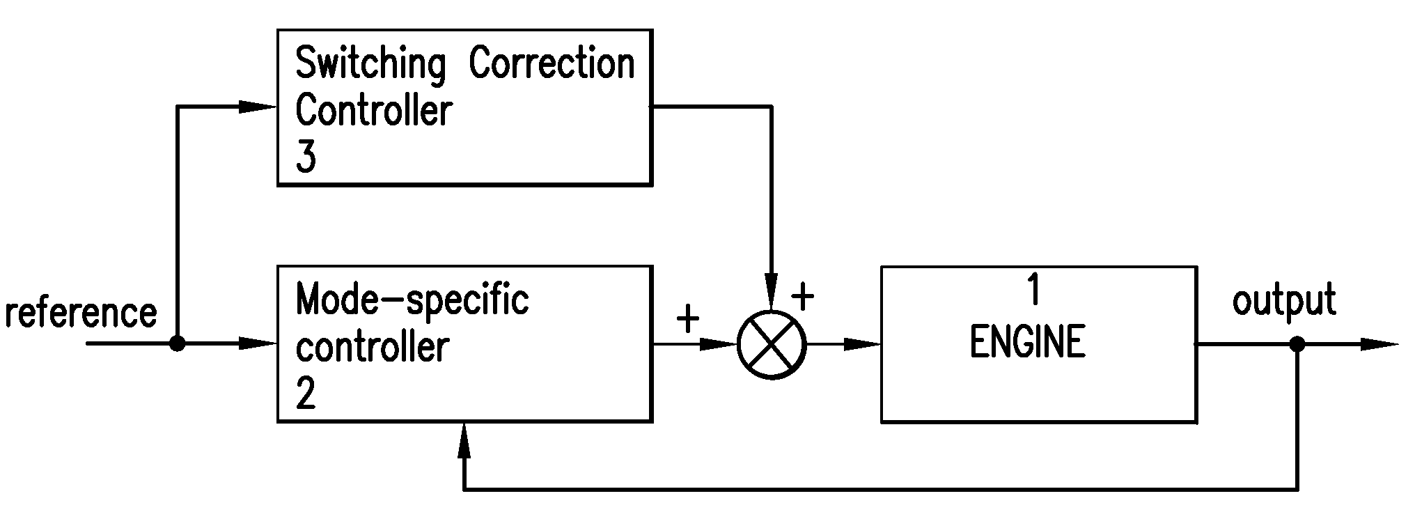
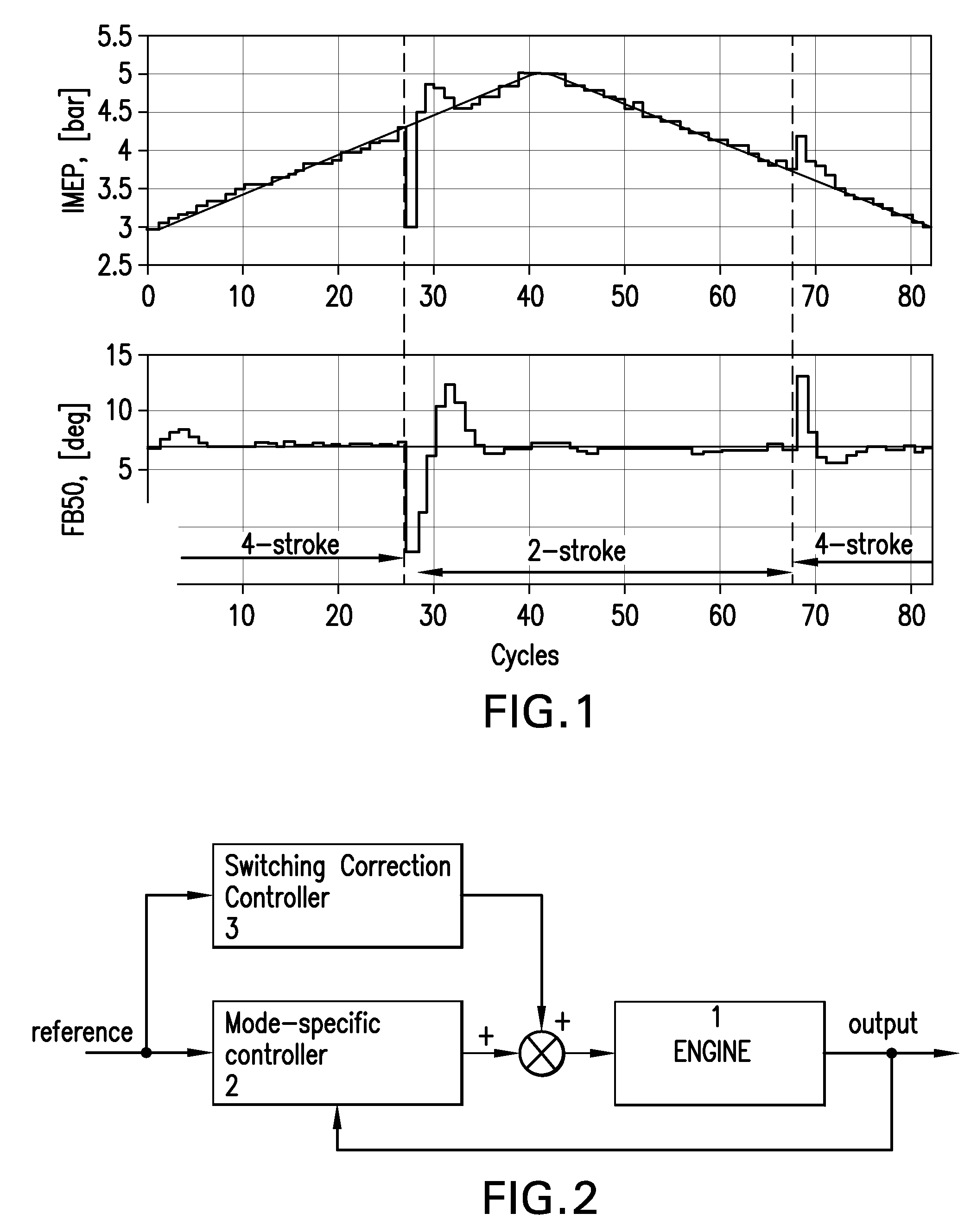
[0016]As shown in FIG. 1, switching between 2-stroke and 4-stroke modes results in oscillations in engine outputs, i.e., the IMEP (upper chart) and the combustion phasing (lower chart). As mentioned above, the engine is controlled so as to switch between the 2-stroke and the 4-stroke modes at the output in IMEP approximately equal to 4 bar. The combustion phasing in both the 2-stroke and the 4-stroke HCCI modes, as well as during switching, is regulated to 7 degrees TDC and is measured at a middle point of the combustion reaction (denoted in FIG. 1 as “MFB50”). The oscillations occur mainly due to differences in gas temperatures and concentrations of species inside engine cylinder between 2-stroke and 4-stroke modes for a given output. More particularly, in the switching from the 4-stroke to the 2-stroke mode, the first 2-stroke cycle following the last 4-stroke cycle is started with the initial conditions which differ from the initial conditions corresponding to the normal 2-stroke...


PUM


Abstract

Engine correction inputs to control oscillation in an engine output in a transition between 2-stroke and 4-stroke engine cycle modes of an HCCI engine are determined as follows: for each mode, valve timings which modify the engine output the most upon switching are determined, and a linear engine system model is defined at least partially based on the determined valve timings, which model provides mappings relating initial conditions of the engine and the engine correction inputs to outputs of the engine; initial conditions of the engine corresponding to a switching point for switching between the two modes are determined; desired engine output conditions upon switching between the two modes are specified; and the engine correction inputs are determined by using the determined initial conditions, the desired engine output conditions, and the linear engine system model corresponding to the engine cycle mode in effect upon switching.

Description

BACKGROUND OF THE INVENTION[0001]1. Field of Invention[0002]The present invention relates to a control system and method for controlling switching between 2-stroke and 4-stroke modes of Homogeneous Charge Compression Ignition (HCCI) engine.[0003]2. Description of Related Art[0004]Homogeneous Charge Compression Ignition (HCCI) technology provides an improvement in efficiency and significant reduction in emissions in comparison to Spark Ignition (SI) and Compression Ignition (CI) internal combustion technologies. The improved fuel economy of the HCCI engines is explained by a high dilution of charge and low throttling losses, which simultaneously results in lower Carbon Monoxide (CO) emissions. In addition, the HCCI engine achieves reduction of Nitrous Oxides (NOx) emissions by about two orders of magnitude in comparison to conventional SI and CI diesel engines, which reduction results from much lower combustion temperatures due to the high dilution of fresh charge.[0005]One of the ma...

Claims


Application Information

Patent Timeline
Patent Type & Authority Applications(United States)
IPC IPC(8): F02B69/06
CPCF01L1/34F01L1/38F01L2710/003F02B69/06F02D41/1401F02D41/1406Y02T10/128F02D41/3058F02D41/307F02D2041/1415F02D2041/1423F02D2041/1433F02D41/3035Y02T10/12
Inventor SUBBOTIN, MAKSIMPARK, SUNGBAEAHMED, JASIMKOJIC, ALEKSANDARCHATURVEDI, NALINCOOK, DAVID
Owner ROBERT BOSCH GMBH
Why Eureka
Try Eureka