Clamping or spreading tool

a technology which is applied in the field of clamping and/or spreading tool, can solve the problems of large space requirement, unfavorable use of known drives, and unfavorable use of tools, and achieves uniform closing motion, space dimension, and weight reduction

Active Publication Date: 2010-11-04
IRWIN IND TOOL CO
View PDF100 Cites 8 Cited by
  • Summary
  • Abstract
  • Description
  • Claims
  • Application Information

AI Technical Summary

Benefits of technology

[0007]It is an object of the invention to overcome the disadvantages of the state of the art, providing especially a drive for a clamping and / or spreading tool for especially continuous displacement of a push or pull rod, the dimensions in space of the clamping and / or spreading tool being small and the weight lower, and especially uniform closing motion with especially a uniform closing force being warranted.
[0008]A drive wheel adapted to be driven in rotation is provided for cooperation with the push or pull rod. As this rotatable drive wheel does not need a drive or acceleration path extending in longitudinal direction of the push or pull rod, the axial dimension of the clamping and / or spreading tool according to the invention is clearly reduced in comparison with known clamping and / or spreading tools having a corresponding mode of operation. Not only the weight is reduced as a consequence of the small dimensions but also the handling of the clamping and / or spreading tool is facilitated since its actuation, especially that of a stepping gear transmission is not obstructed by portions of the push or pull rod projecting far beyond the support. Especially when space is tight where a clamping or spreading tool is to be used and a handle of the stepping gear transmission is restricted, the clamping and / or spreading tool according to the invention is much easier to manipulate than the known ones. While the known high speed closure mechanism including a compression spring presents further risk of injury to the operator in that he / she may get parts of his / her body squeezed between the coil windings and the propelling forces are released explosively, such potential risks can be eliminated by the measure according to the invention. According to the invention, the drive wheel is operationally coupled to a torsion spring for rotational driving. The torsion spring is a mechanical prime mover having a mechanical energy reservoir. In comparison with an electrical alternative, this mechanical prime mover has the advantage of not being dependent on electrical power supply. The wheel driven by the torsion spring, according to the invention, is adapted to enter into torque transmitting engagement with the push or pull rod to displace the same. The drive wheel can be engaged with the push or pull rod to transmit torque.

Problems solved by technology

It is a disadvantage of this quick-lock mechanism that much space is required to offer the quick-lock mechanism the path needed for unfolding the driving power stored.
As the compression spring assembly needs a long drive path for the driving power to unfold, clamping and / or spreading tools of this kind have not only a great axial extension but also great weight, making such tools unwieldy to handle.
Above all, the known drive bears a risk of injury since the movable jaw closes explosively.
The damping means may achieve its damping characteristic by generating friction loss.

Method used


Image

  • Clamping or spreading tool
  • Clamping or spreading tool
  • Clamping or spreading tool

Examples


Embodiment Construction

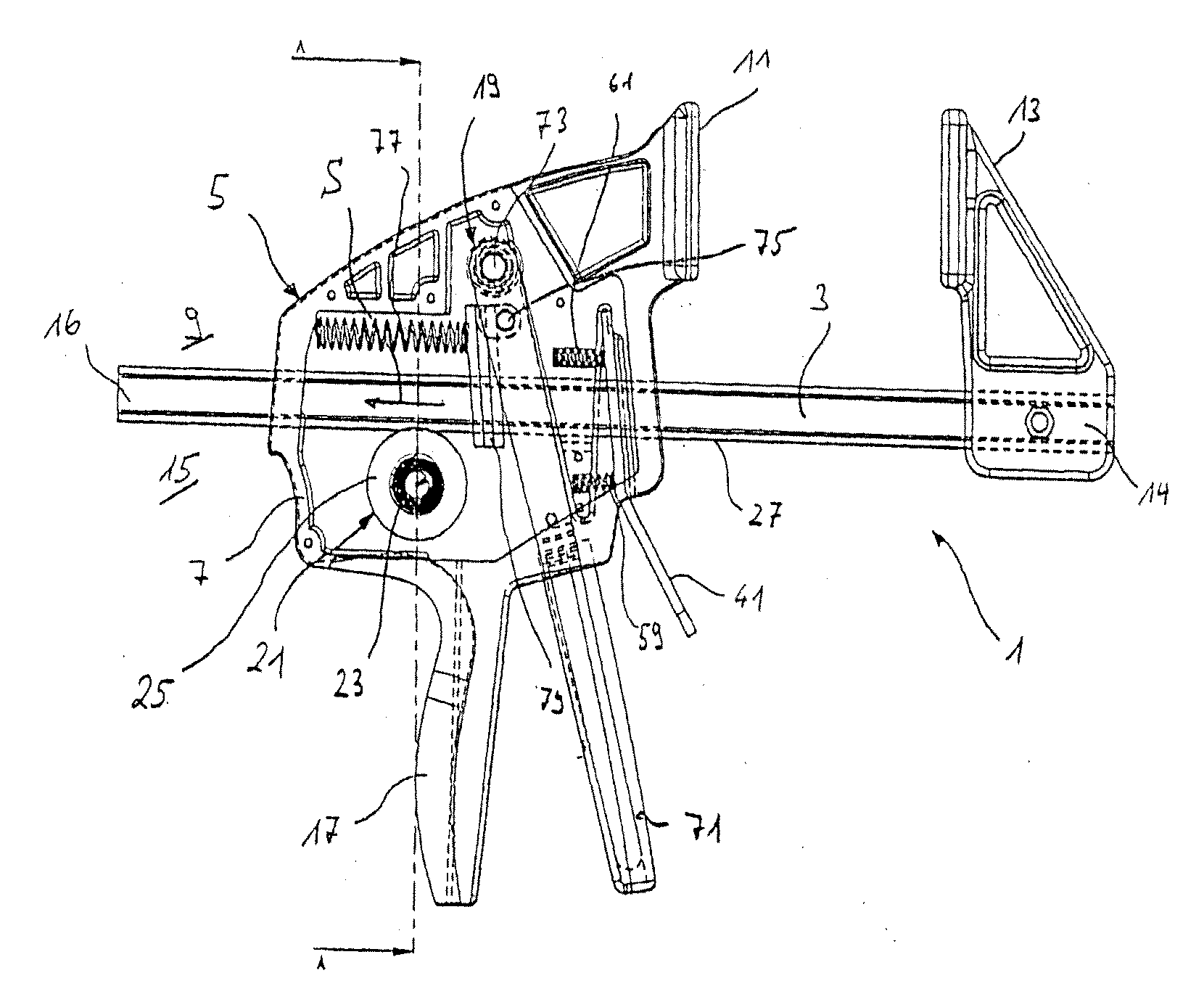
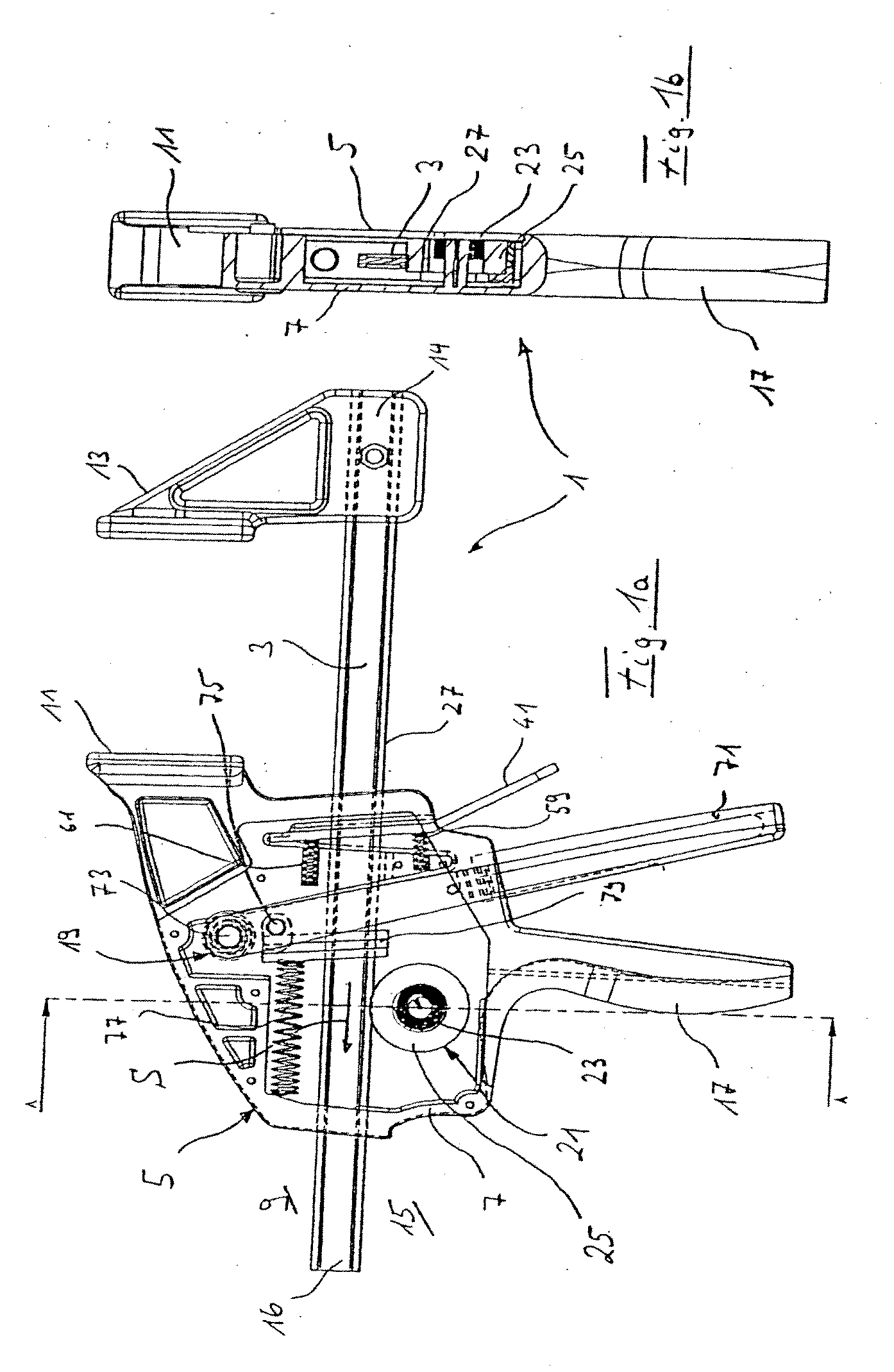
[0071]The preferred design of a clamping and / or spreading tool 1 illustrated in FIGS. 1a and 1b comprises a push or pull rod 3 movably supported on a support 5 for displacement in longitudinal direction of the rod. The support 5 comprises a closed casing 7, a fixed clamping jaw 11 being provided at the clamping side 9 of the push or pull rod 3, diametrically opposite a movable clamping jaw 13 which is removably attached to one end 14 of the push or pull rod 3.

[0072]FIG. 1a shows the clamping mode of the clamping and / or spreading tool 1. The clamping and / or spreading tool 1 will be in spreading mode when the movable jaw 13 is secured to the opposite end 16 of the push or pull rod 3.

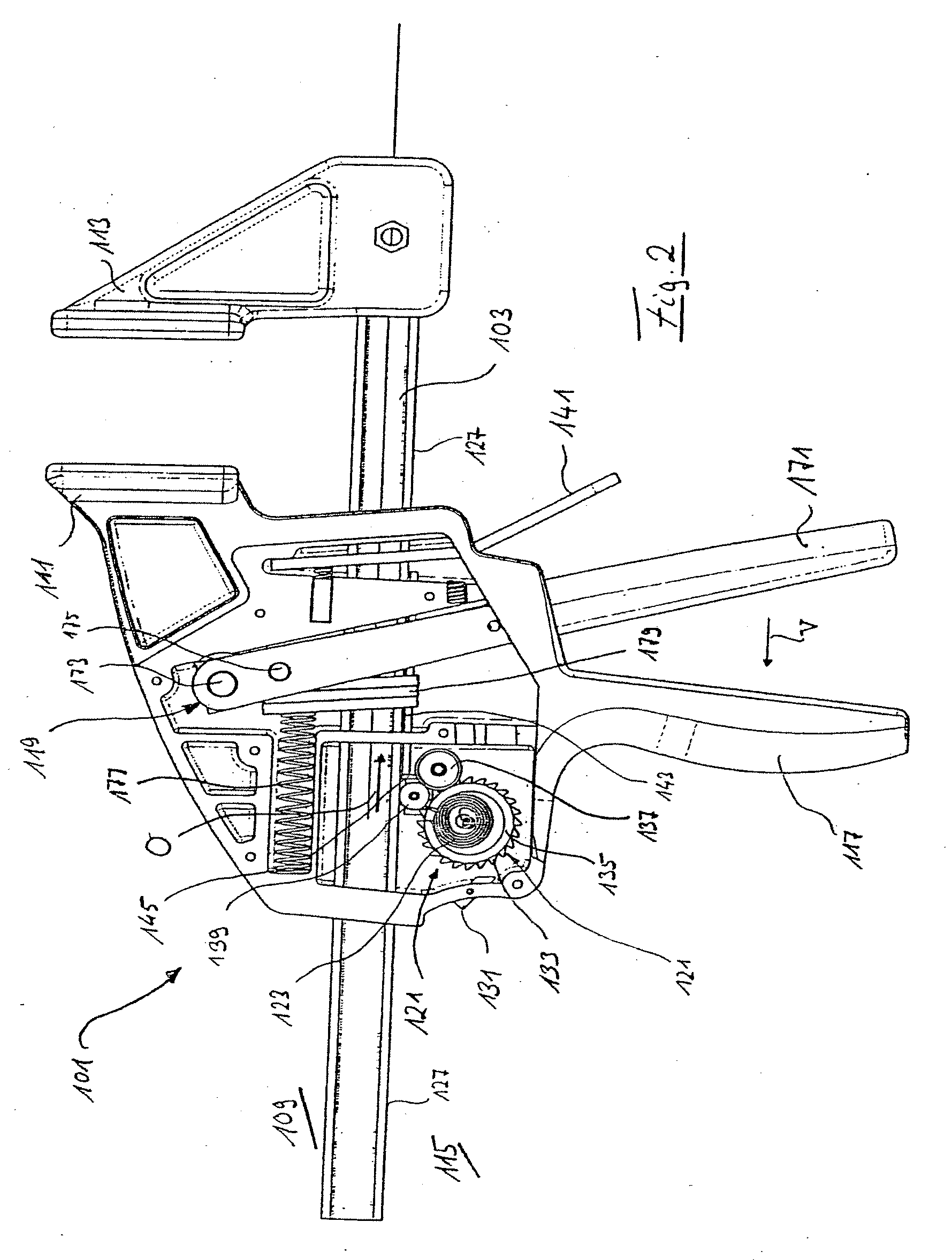
[0073]At the actuating side 15 of the push or pull rod 3, opposite the clamping side 9, a handle 17 is integrally fixed to the support 5 for the clamping and / or spreading tool to be held by one hand. In addition, the support 5 carries a stepping gear transmission 19, to be explained in greater detail below...


PUM

PropertyMeasurementUnit
forceaaaaaaaaaa
axis of rotationaaaaaaaaaa
potential energyaaaaaaaaaa

Abstract

A clamping and / or spreading tool comprises a drive for displacement of a push or pull rod to which a movable jaw is fixed with respect to a support carrying a stationary jaw in longitudinal direction of the push and pull rod, the drive comprising a torsion spring and being adapted to enter torque transmitting engagement with the push or pull rod for displacement of the same.

Description

RELATED APPLICATIONS[0001]This application is a continuation of and claims priority from U.S. patent application Ser. No. 11 / 936,439, filed on Nov. 7, 2007, which is a continuation of and claims priority benefit from U.S. patent application Ser. No. 10 / 576,091, filed on Apr. 11, 2006, which is a U.S. national phase of PCT EP / 2004 / 014179 filed on Dec. 13, 2004, which claims priority benefit of: DE 103 58 301.7 filed on Dec. 12, 2003; DE 103 58 296.7 filed on Dec. 12, 2003; DE 103 58 302.5 filed Dec. 12, 2003; DE 103 58 303.3 filed Dec. 12, 2003; DE 103 58 304.1 filed Dec. 12, 2003; and DE 103 58 291.6 filed Dec. 12, 2003, the specifications of which are hereby incorporated by reference.BACKGROUND[0002]1. Field of the Invention[0003]The invention relates to a clamping and / or spreading tool comprising a drive for displacement of a push or pull rod to which a movable jaw is fixed with respect to a support carrying a stationary jaw, in longitudinal direction of the push or pull rod.[0004...

Claims


Application Information

Patent Timeline
Patent Type & Authority Applications(United States)
IPC IPC(8): B25B5/06B23P11/00F03G1/00F03G1/02
CPCB25B5/068F03G1/02Y10T74/20049Y10T29/49826F16C1/18
Inventor GEIER, MANFREDSTRAUSS, RALFREED, PHIL
Owner IRWIN IND TOOL CO
Why Eureka
Try Eureka