High speed internal permanent magnet machine

a permanent magnet machine, high-speed technology, applied in the direction of magnetic circuit rotating parts, magnetic circuit shape/form/construction, stator/rotor body manufacturing, etc., can solve the problems of reducing machine power density and reducing machine efficiency, and achieve high power density and efficiency.

Active Publication Date: 2010-11-04
GENERAL ELECTRIC CO
View PDF10 Cites 85 Cited by
  • Summary
  • Abstract
  • Description
  • Claims
  • Application Information

AI Technical Summary

Problems solved by technology

The increased thickness leads to more magnet flux leakage into the multiple bridges and center posts, which leakage significantly reduces the machine power density, resulting in decreased efficiency of the machine.

Method used


Image

  • High speed internal permanent magnet machine
  • High speed internal permanent magnet machine
  • High speed internal permanent magnet machine

Examples


Embodiment Construction

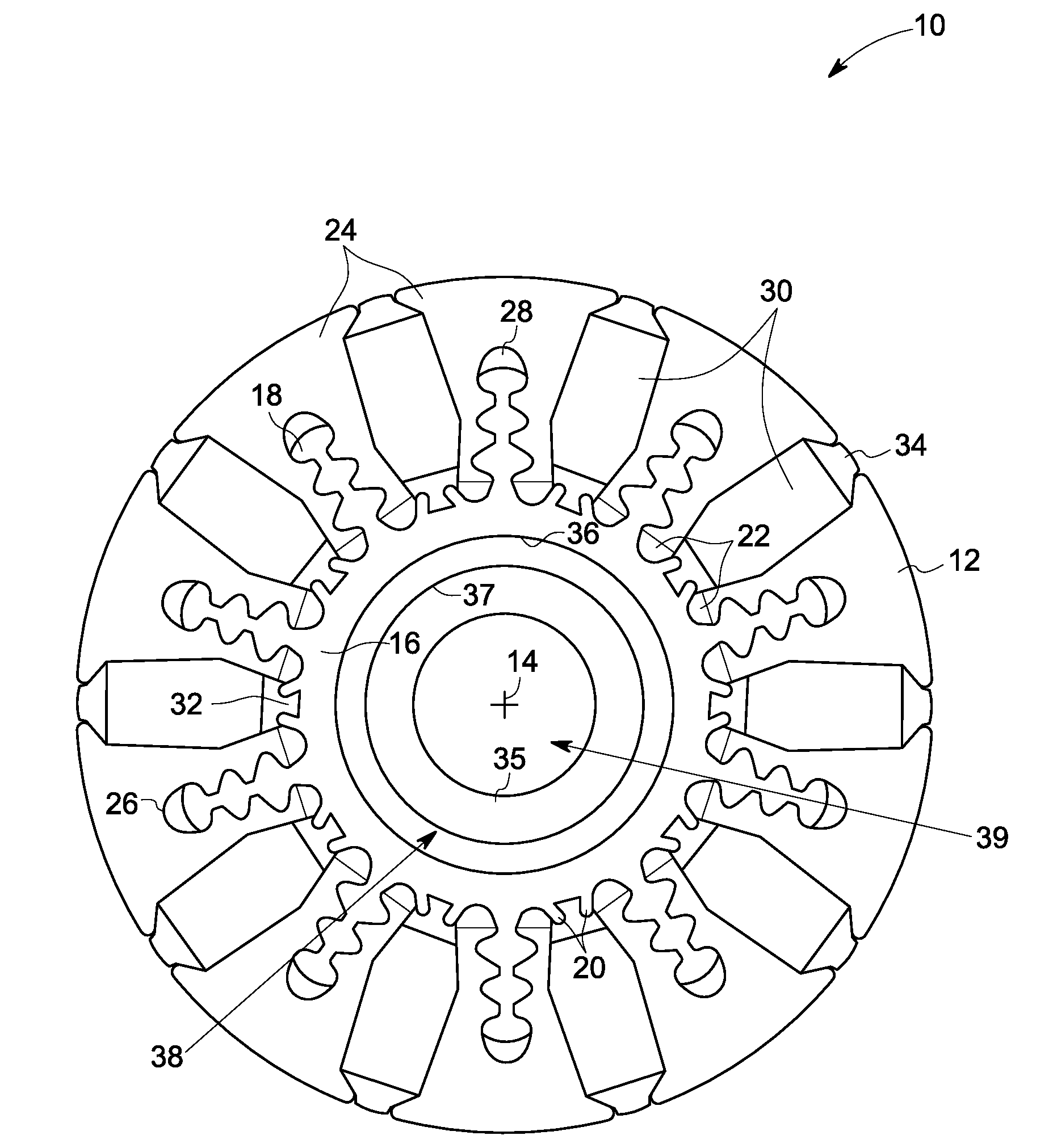
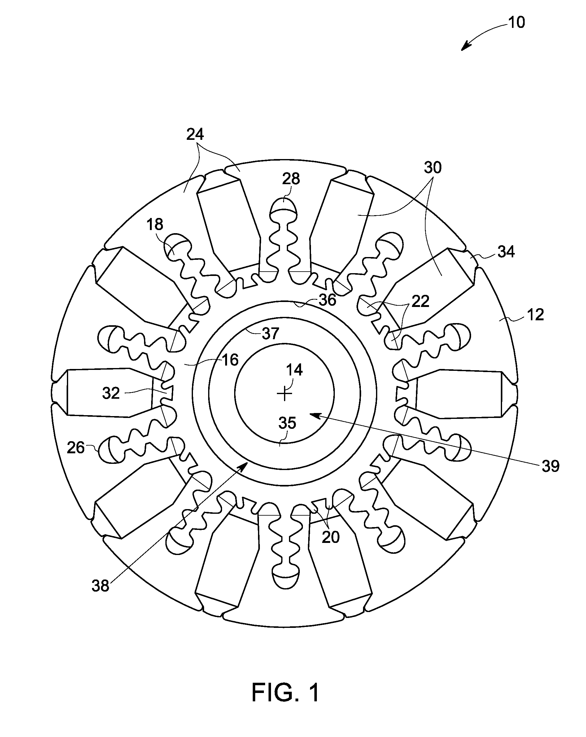
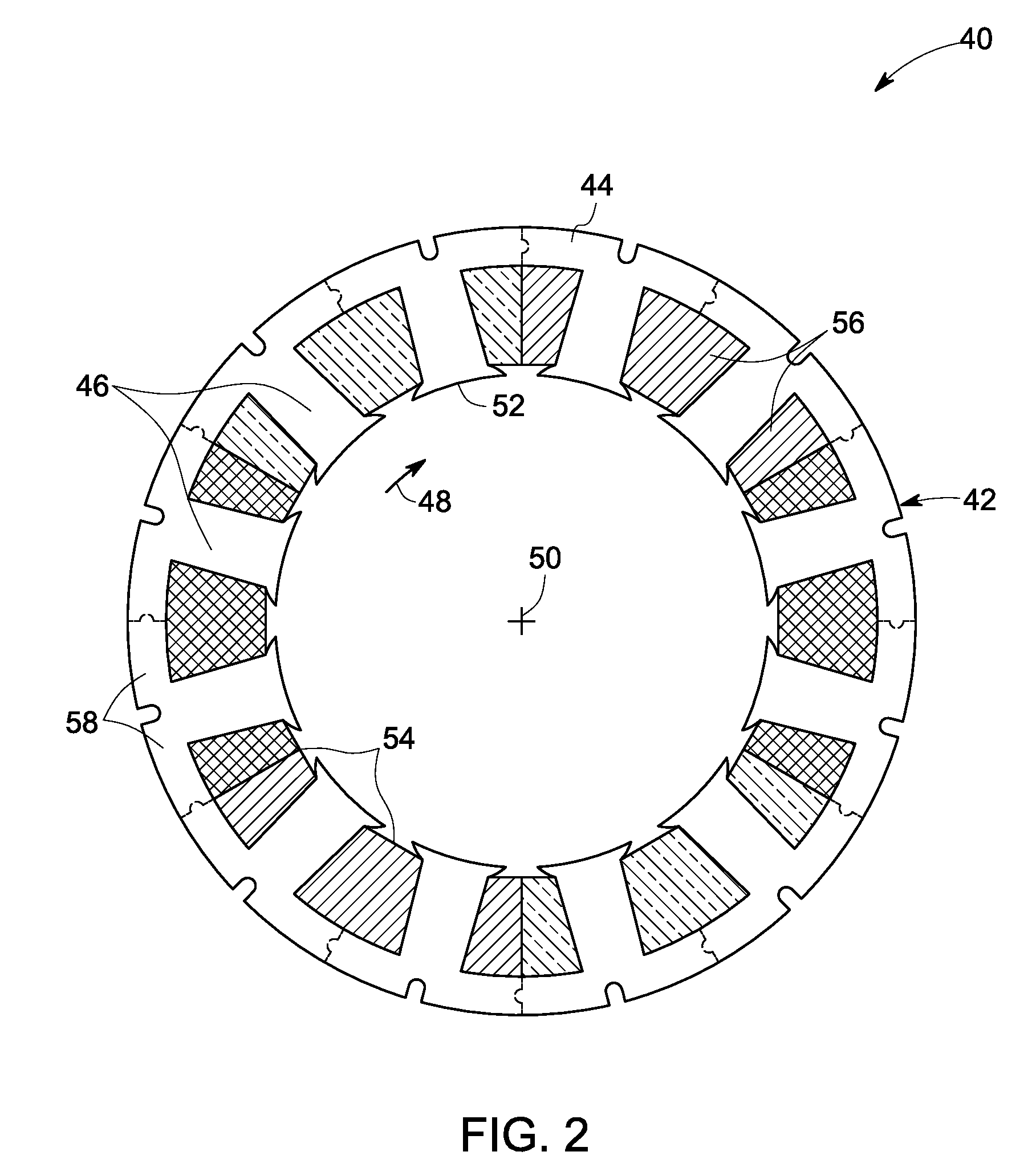
[0019]As discussed in detail below, embodiments of the invention are directed towards an IPM machine and a method for providing the same. The IPM machine includes a stack of laminations preferably shaped in a dovetail configuration for engagement with multiple permanent magnets, which laminations are mounted in multiple protrusions circumferentially around a shaft in a rotor assembly. As used herein, the term ‘dovetail’ refers to fan-shaped features that form a tight interlocking joint. In particular, the present invention is directed to a high-speed IPM machine with high power-density ranging between about 1.375 kWpeak / Kg to about 1.57 kWpeak / Kg.

[0020]When introducing elements of various embodiments of the present invention, the articles “a,”“an,”“the,” and “said” are intended to mean that there are one or more of the elements. The terms “comprising,”“including,” and “having” are intended to be inclusive and mean that there may be additional elements other than the listed elements....


PUM

PropertyMeasurementUnit
magnetic fieldaaaaaaaaaa
non-metallicaaaaaaaaaa
mechanical stressaaaaaaaaaa

Abstract

An internal permanent magnet (IPM) machine is provided. The IPM machine includes a stator assembly and a stator core. The stator core also includes multiple stator teeth. The stator assembly is further configured with stator windings to generate a magnetic field when excited with alternating currents and extends along a longitudinal axis with an inner surface defining a cavity. The IPM machine also includes a rotor assembly and a rotor core. The rotor core is disposed inside the cavity and configured to rotate about the longitudinal axis. The rotor assembly further includes a shaft. The shaft further includes multiple protrusions alternately arranged relative to multiple bottom structures provided on the shaft. The rotor assembly also includes multiple stacks of laminations disposed on the protrusions and dovetailed circumferentially around the shaft. The rotor assembly further includes multiple permanent magnets for generating a magnetic field, which interacts with the stator magnetic field to produce torque. The permanent magnets are disposed between the stacks. The rotor assembly also includes multiple bottom wedges disposed on the bottom structures of the shaft and configured to hold the multiple stacks and the multiple permanent magnets.

Description

STATEMENT REGARDING FEDERALLY SPONSORED RESEARCH & DEVELOPMENT[0001]This invention was made with Government support under contract number DE-FC26-07NT43122 awarded by U.S. Department of Energy. The Government has certain rights in the invention.BACKGROUND[0002]The invention relates generally to an internal permanent magnet machine and more particularly, to a high-speed internal permanent magnet machine with high power-density.[0003]Internal Permanent Magnet (IPM) Machines such as IPM motors or generators have been widely used in a variety of applications including aircraft, automobiles and industrial usage. However, IPM machines are currently the clear favorite in hybrid automotive applications. Therefore, a requirement for lightweight and high power density IPM machines has resulted in the design of higher speed motors and generators to maximize the power to weight ratios. Hence, the trend is increasing acceptance of IPM machines offering high machine speed, high power density, red...

Claims


Application Information

Patent Timeline
Patent Type & Authority Applications(United States)
IPC IPC(8): H02K1/28H02K1/32H02K15/03
CPCH02K1/2773Y10T29/49012H02K7/1838H02K1/32
Inventor ALEXANDER, JAMES PELLEGRINOEL-REFAIE, AYMAN MOHAMED FAWZILOKHANDWALLA, MURTUZASHAH, MANOJ RAMPRASADVANDAM, JEREMY DANIEL
Owner GENERAL ELECTRIC CO
Why Eureka
Try Eureka