

Power converter and power unit
a power converter and power unit technology, applied in the direction of dc-ac conversion without reversal, process and machine control, instruments, etc., can solve the problems of three-phase output not making electric capacity sufficiently small under the existing circumstances, and extremely short life of aluminum electrolytic capacitors
- Summary
- Abstract
- Description
- Claims
- Application Information
AI Technical Summary
Benefits of technology
Problems solved by technology
Method used
Image

Examples
first embodiment
(First Embodiment)
[0075]FIG. 5 is a view showing a first embodiment of the present invention.
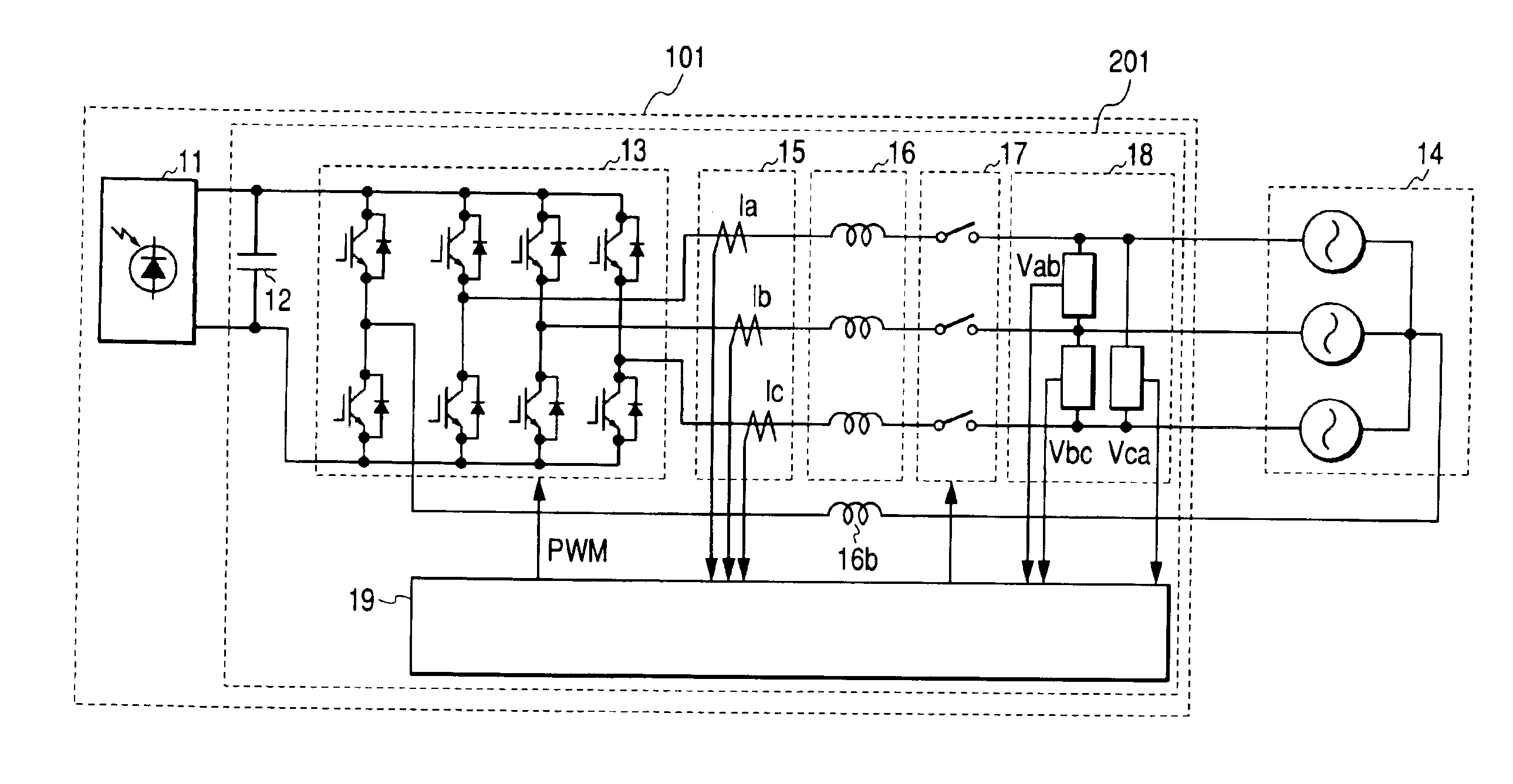
[0076]A power unit 101 is constituted by a solar cell 11 and a power converter 201 connected to this solar cell 11. The power converter 201 comprises smoothing capacitor 12 connected in parallel with the output of the solar cell 11, a switching circuit 13 for converting a direct current power generated by the solar cell 11 into an three phase alternating current power, and a linkage reactor 16 and a neutral wire reactor 16b for smoothing the current, and outputs the three-phase alternating current power to a three-phase system 14 of a three phase four wire type through an opening and closing means 17. This is a so-called system-tie photovoltaic power generation system comprising the solar cell and a system-tie inverter. Further, this power generation system comprises current detection means 15 for detecting the currents Ia, Ib and Ic of each phase, voltage detection means 18 for detecting th...
second embodiment
(Second Embodiment)
[0085]FIG. 6 is a view showing a second embodiment of the present invention, and has the same constitution as FIG. 5 showing the first embodiment for the most part. Those attached with the same reference numerals denote the same members. This second embodiment is different from the first embodiment in that a DC / DC converter 21 is located between a solar cell 11 and a smoothing capacitor 12. Reference numeral 202 denote a power converter and reference numeral 102 a power unit.
[0086]The DC / DC converter 21, as shown in FIG. 6, connects a solar cell 11 and smoothing capacitor 22 in parallel and receives the direct current power of the solar cell 11, and at the same time, constitutes a so-called boosting chopper circuit for boosting the direct current voltage by a boosting coil 23, switching means 24 and a diode 25 for use of protecting a reverse current, and boosts the direct current voltage from the solar cell 11 to a desired voltage so as to be outputted to the smoo...
third embodiment
(Third Embodiment)
[0089]FIG. 7 is a view showing a third embodiment of the present invention, and reference numerals same as FIG. 5 denote the same members. Reference numeral 203 denotes a power converter.
[0090]The point in which a power unit 103 of the present embodiment is sharply different from the first embodiment is that the power unit comprises two single-phase inverters, which output to single-phase resistance loads 34d and 34e, respectively. The input of each single-phase inverter uses a common smoothing capacitor 12, and is converted into a single-phase alternating current by single-phase bridges 33d and 33e respectively, and outputs a smooth current to the resistance loads 34d and 34e respectively by a linkage reactor 16. The output currents Id and Ie of each single-phase inverter are detected by current detection means 15, and the output voltages Vd and Ve applied to each resistance loads 34d and 34e are detected by voltage detection means 18, and both the output currents...
PUM
 Abstract
Description
Claims
Application Information