Gun flash hider

a gun and flash technology, applied in the field of gun flash hiders, can solve the problems of reducing stability and shooting accuracy when using the gun or cannon, affecting the firing plane of the firearm or cannon, and the location of the shooter firing the gun is easily exposed, so as to reduce the amount of flame and recoil force, increase stability and shooting accuracy, and reduce pressure

Inactive Publication Date: 2010-11-11
TROIKA INT
View PDF20 Cites 26 Cited by
  • Summary
  • Abstract
  • Description
  • Claims
  • Application Information

AI Technical Summary

Benefits of technology

[0006]A primary objective of the present invention is to provide a gun flash hider able to reduce sonic boom volume, amount of flame and recoil force produced when firing a gun, and which enables increasing stability and shooting accuracy when using the gun.
[0008]In conclusion, the inventor of the present invention in its use of aerodynamic principles provides additional expansion decompression and flow diversion decompression interior of the gun flash hider of the present invention, as well as unique aerodynamic technology of gas diversion discharge to substantially reduce sonic boom volume, amount of flame and recoil force when firing a bullet or shell, thereby thoroughly improving the exasperating shortcomings evident when firing the original firearm and cannon. Moreover, because of the pre-discharge decompressions, thereby reducing single discharge amount of high-temperature high-pressure gas after combustion of the gunpowder, and reducing discharge pressure, thus, the recoil force produced and jerking of the gun when firing is evidently reduced, and consequently stability is also greatly increased when firing.

Problems solved by technology

However, the sonic boom volume and amount of flame produced after installing such a flash hider of the prior art are still substantial, with the result that the location of the shooter firing the gun is easily exposed when firing in insufficient light or at night.
Hence, jerking of the firing plane of the firearm or cannon is affected, and stability and shooting accuracy is reduced when using the gun or cannon.

Method used


Image

  • Gun flash hider
  • Gun flash hider
  • Gun flash hider

Examples


Embodiment Construction

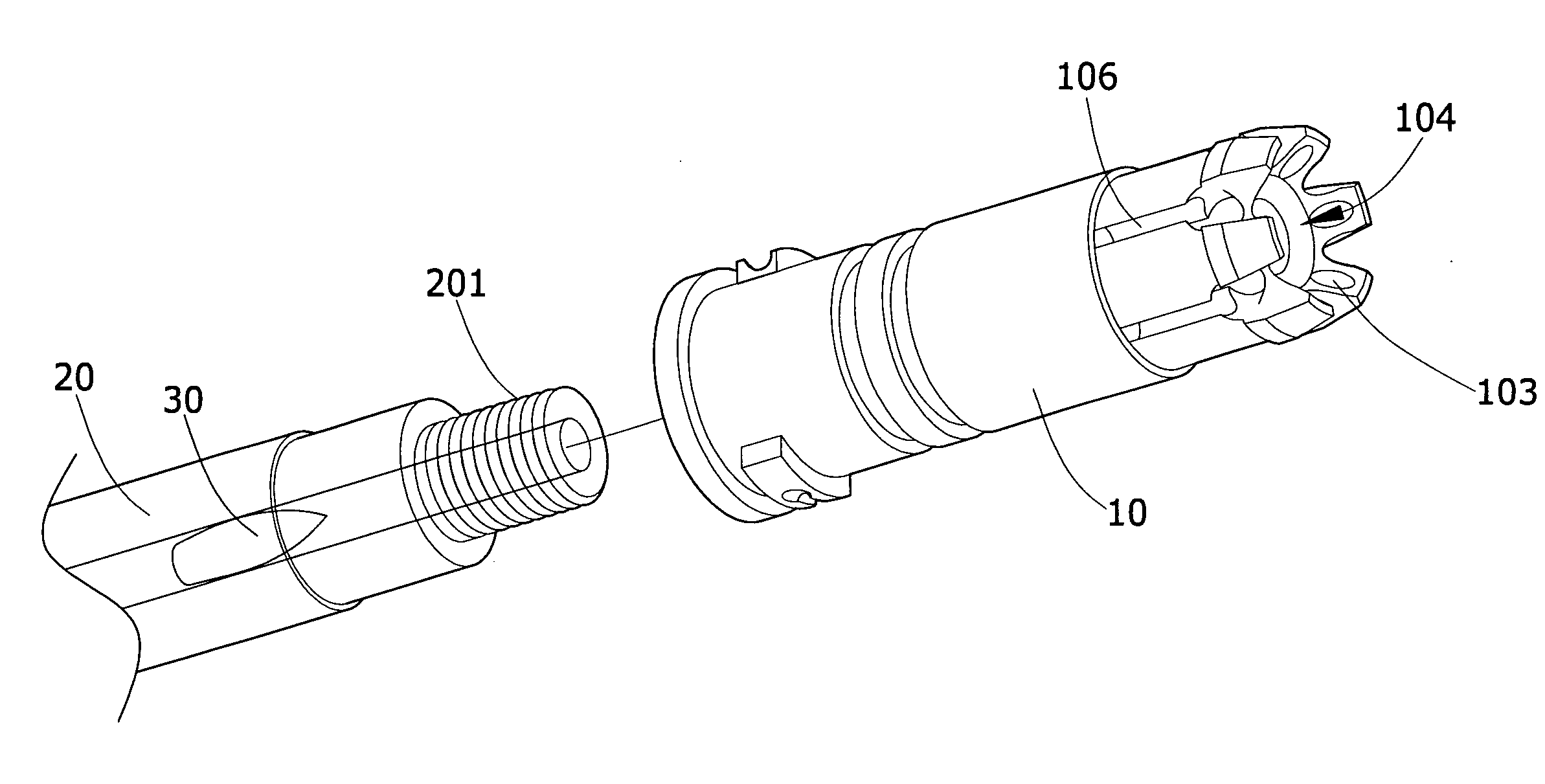
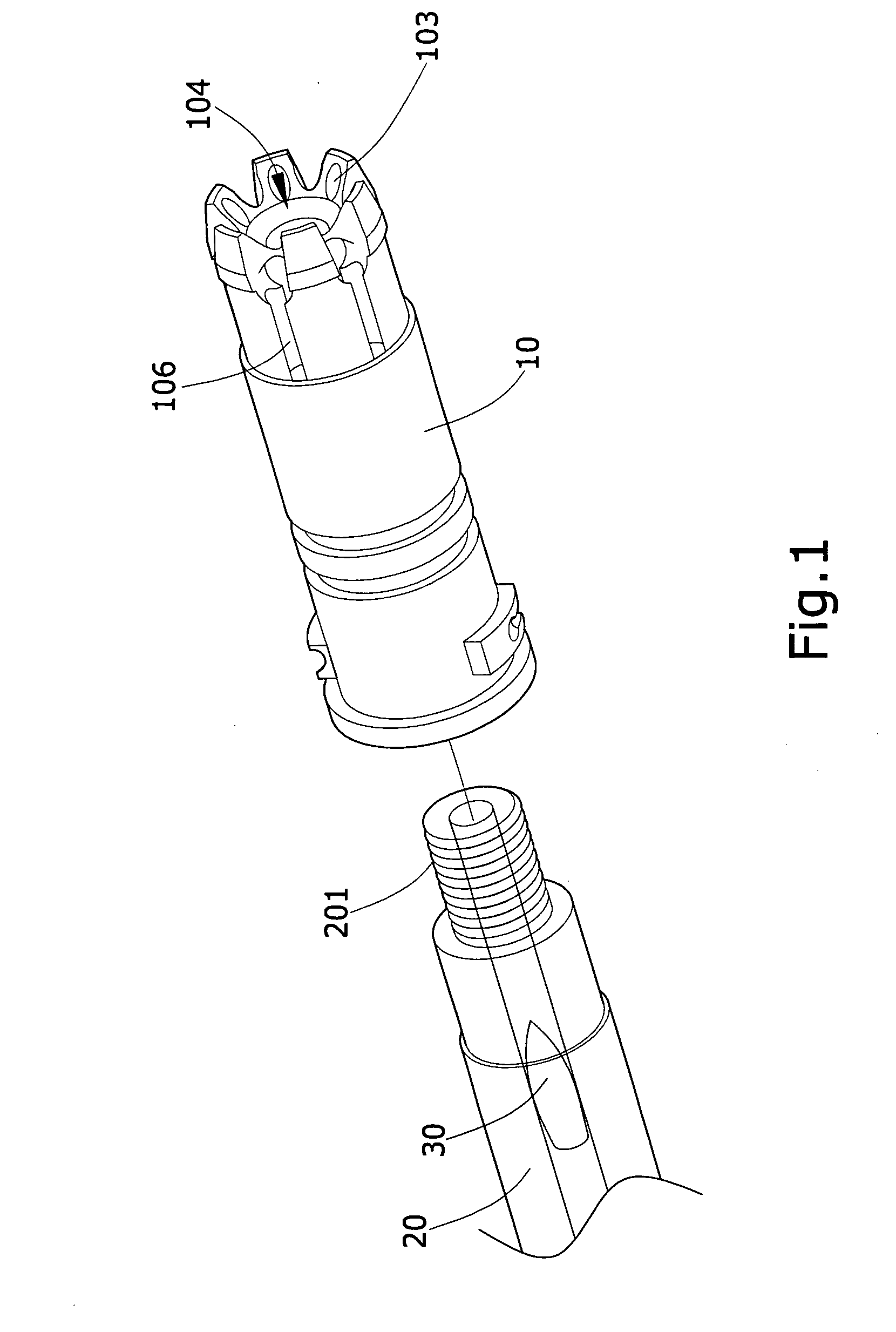
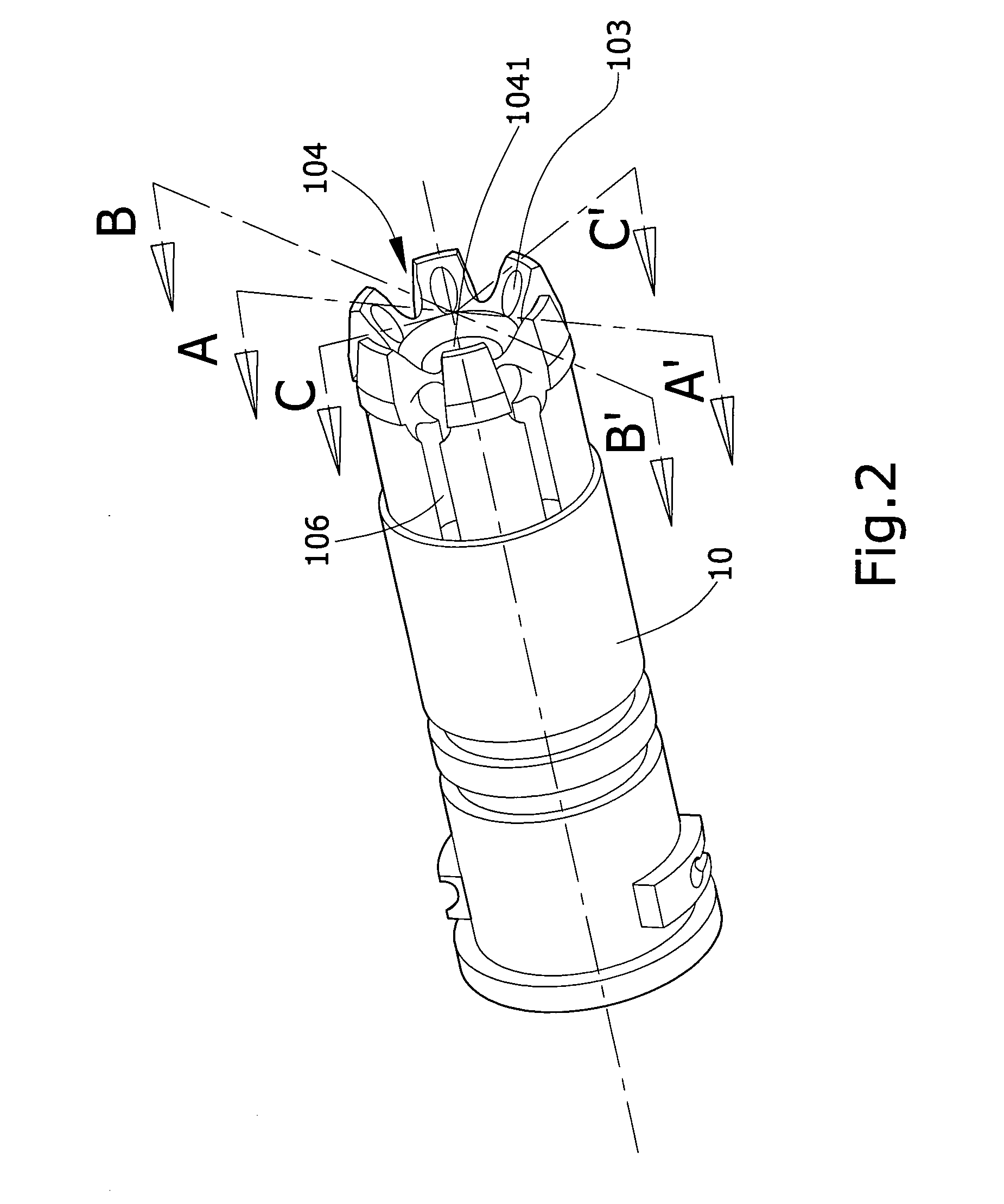
[0017]Referring to FIG. 1, which shows a schematic view depicting joining of a preferred embodiment of the present invention to a gun, wherein a gun flash hider 10 of the present invention is used in combination with a common firearm or cannon. Taking a firearm as an example a front end of a barrel 20 of the firearm forms a threaded portion 201 correspondingly enabling assembly of the gun flash hider 10 of the present invention thereto. After joining the gun flash hider 10 of the present invention to the barrel 20, when a bullet 30 is fired, then the high-temperature, high-pressure gas produced from combustion explosion of the gunpowder, after multiple expansion decompression, flow diversion decompression and exhaust decompression, the high-temperature high-pressure gas is sequentially discharged from first exhaust passages 103 and second exhaust passages 106 located at the surface of the gun flash hider 10 and an exhaust head 104, where the gas integrates with the atmosphere at the...


PUM


Abstract

A gun flash hider, formed to include a first expansion chamber, a first flow divider, a plurality of first exhaust passages, an exhaust head, a second expansion chamber, a plurality of second exhaust passages and a second flow divider, whereby high-temperature high-pressure gas produced after firing a bullet undergoes two expansion decompressions and two flow diversion decompressions, through which the gas is sequentially discharged from the first exhaust passages and the second exhaust passages, thereby substantially reducing sonic boom volume, amount of flame and recoil force produced when firing the bullet, and increasing stability and shooting accuracy when using a gun.

Description

BACKGROUND OF THE INVENTION[0001](a) Field of the Invention[0002]A gun flash hider fitted to the front end of a firearm or cannon, which is able to reduce sonic boom volume, amount of flame and recoil force produced when firing the firearm or cannon.[0003](b) Description of the Prior Art[0004]Currently, the flash hiders used in the most commonly seen firearms and cannons are of circular tube form, an internal penetrating space of which assumes a conical shape, and the tubular walls of the flash hider is provided with a plurality of strip exhaust passages. After firing the gun or cannon, the energy generated from the combustion explosion of the gunpowder is used to project a bullet. However, a large amount of gas is instantaneously released after combustion explosion of the gunpowder, and when the high-temperature high-pressure gas passes through the flash hider, then the conical shaped inner barrel and the strips of exhaust passages on the barrel walls are used to effect a one-time ...

Claims


Application Information

Patent Timeline
Patent Type & Authority Applications(United States)
IPC IPC(8): F41A21/34
CPCF41A21/34
Inventor HUNG, YI-HSIEN
Owner TROIKA INT
Why Eureka
Try Eureka