

Method for operating a laser as an ignition device of an internal combustion engine
- Summary
- Abstract
- Description
- Claims
- Application Information
AI Technical Summary
Benefits of technology
Problems solved by technology
Method used
Image

Examples
Embodiment Construction
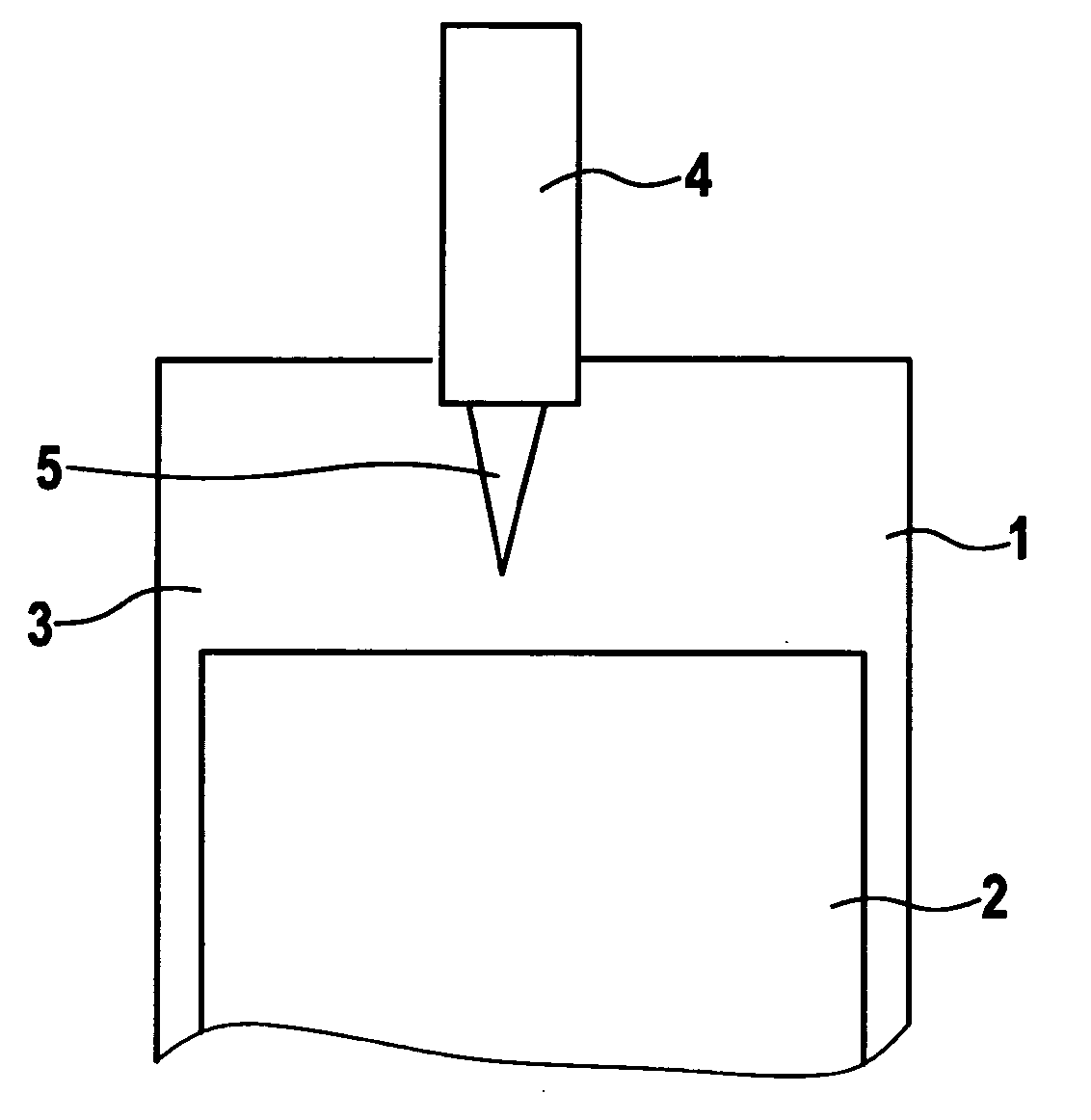
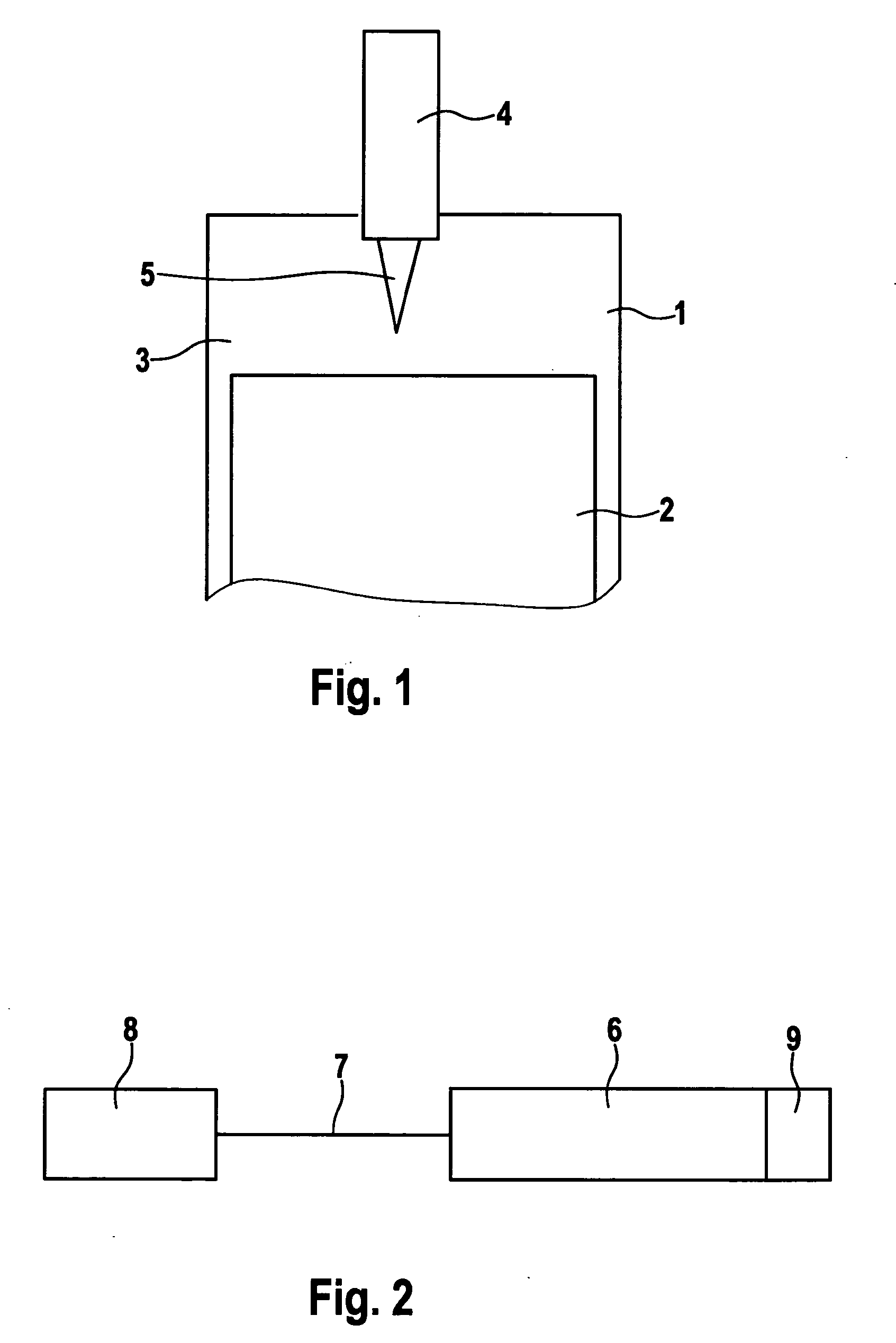
[0016]FIG. 1 shows schematically a cylinder of an internal combustion engine, in which a piston 2 is movably situated. Cylinder 1 and piston 2 form a combustion chamber 3. A combustible mixture is applied to combustion chamber 3, through an intake duct and appropriate valves, which is ignited. This causes a pressure rise in combustion chamber 3, which causes a motion of piston 2. The motion of piston 2 is transformed into a rotational motion, by a crankshaft, which is then used to drive a motor vehicle or the like. In the schematic representation of FIG. 1, the crankshaft, the fresh air channel, the exhaust air channel, corresponding valves and the like are not shown, since this is not essential for an understanding of the present invention. In the representation of FIG. 1, a usual Otto engine is involved. The ignition of the combustible fuel / air mixture present in combustion chamber 3 takes place using a laser 4, which applies a focused laser beam 5 to combustion chamber 3, and thu...
PUM
 Abstract
Description
Claims
Application Information