Sensor system and method for operating a sensor system

a sensor system and sensor technology, applied in the field of sensor systems, can solve the problems of time delay in the evaluation of a plurality of sensor elements, and achieve the effects of simple and cost-effective implementation, increased and marked increase in the readout speed of the sensor system

Inactive Publication Date: 2014-04-15
ROBERT BOSCH GMBH
View PDF14 Cites 0 Cited by
  • Summary
  • Abstract
  • Description
  • Claims
  • Application Information

AI Technical Summary

Benefits of technology

[0005]The sensor system and the associated method of the present invention have the advantage that, using comparatively simple means, the readout speed of the sensor system is markedly increased compared to the related art without the occurrence of temporal artefacts. This is achieved by combining sensor elements to form sensor-element blocks which are evaluated in parallel and which are interlaced. An interlaced configuration of two sensor-element blocks in accordance with the present invention means, in particular, that at least one sensor element of one sensor-element block is disposed between two sensor elements of another sensor-element block. By splitting the sensor elements into a plurality of sensor-element blocks able to be evaluated in parallel, the image rate and therefore the readout speed of the sensor system is increased. At the same time, the interlacing of the sensor-element blocks prevents the occurrence of temporal artefacts, since sensor elements which lie comparatively close together, and especially adjacent sensor elements are assigned to different sensor-element blocks, and consequently are evaluated in parallel. Therefore, time delays in the evaluation of a plurality of sensor elements occur merely in the case of sensor elements situated comparatively far apart. Temporal artefacts like, for example, an object moving comparatively quickly through a visual field of the sensor system no longer being perceived as moving straight or continuously, but rather as moving erratically or in delayed fashion, are therefore prevented using means which are comparatively simple and cost-effective to implement, while the signal quality remains constant. In contrast, the signal quality would be considerably negatively influenced in response to a mere increase of the image rate. By the assignment of the first sensor element to the first sensor-element block and the third sensor element to the second sensor-element block, a parallel evaluation, particularly of the adjacent first and third sensor elements, is possible in a first method step, the second sensor element disposed comparatively further away from the first sensor element not being evaluated until the second method step. The essentially isochronous evaluation, particularly of the adjacent first and third sensor elements, therefore permits a substantially judder-free evaluation of an object moving comparatively quickly through the visual field of the first and third sensor elements, without impairment of the signal quality.
[0006]According to one further refinement, a fourth sensor element is further assigned to the second sensor-element block, the second sensor element being situated between the third and the fourth sensor element. Particularly advantageously, the second sensor element is therefore situated comparatively close and, in particular, adjacent to the fourth sensor element, so that even in those partial areas of the visual field of the sensor system in which the second and fourth sensor elements are disposed, an essentially isochronous evaluation of the adjacent sensor elements is attained, and according to this principle, temporal artefacts are suppressed in the entire sensor system, i.e., in the entire visual field of the sensor system by the complete interlacing of the sensor-element blocks, and at the same time, the readout speed is increased.
[0007]According to a further development, the sensor system includes a third sensor-element block, to which at least one fifth sensor element is assigned that is disposed between the second and the third sensor element. A higher readout speed of the sensor system is attainable particularly advantageously by the assignment of the fifth sensor element to the third sensor-element block, since in addition to the first and third sensor elements, the fifth sensor element is also able to be read out in the first method step, the positioning of the fifth sensor element between the second and the third sensor element, i.e., thus in the vicinity of the second sensor element, serving to suppress temporal artefacts.
[0008]According to another refinement, additional sensor elements are assigned to additional sensor-element blocks, at least one additional sensor element of each additional sensor-element block being situated between the first sensor element and the second sensor element. The readout speed of the sensor system is increased more and more by the further subdivision of the sensor system into additional sensor-element blocks, since the additional sensor elements are read out along at the same time in each method step. In this context, the interlacing of the additional sensor-element blocks permits the suppression of temporal artefacts.
[0010]According to another development, the sensor elements and the further sensor elements of each column are electroconductively interconnected via first lines, so that each sensor element of a column is able to be evaluated or controlled especially advantageously via the corresponding shared first line, thus reducing the contacting expenditure considerably.
[0013]According to another refinement, the sensor elements include diodes and / or the sensor system includes a sensor for spatially-resolved detection, particularly for the spatially-resolved measurement of temperature, radiation and / or a fingerprint and / or the sensor system includes a sensor for detecting a concentration of gas. Therefore, the readout speed of the sensor system, considerably increased compared to the related art, especially advantageously permits a spatially resolved detection of comparatively short-lived events and / or comparatively rapidly moving objects.

Problems solved by technology

Therefore, time delays in the evaluation of a plurality of sensor elements occur merely in the case of sensor elements situated comparatively far apart.

Method used


Image

  • Sensor system and method for operating a sensor system
  • Sensor system and method for operating a sensor system

Examples


Embodiment Construction

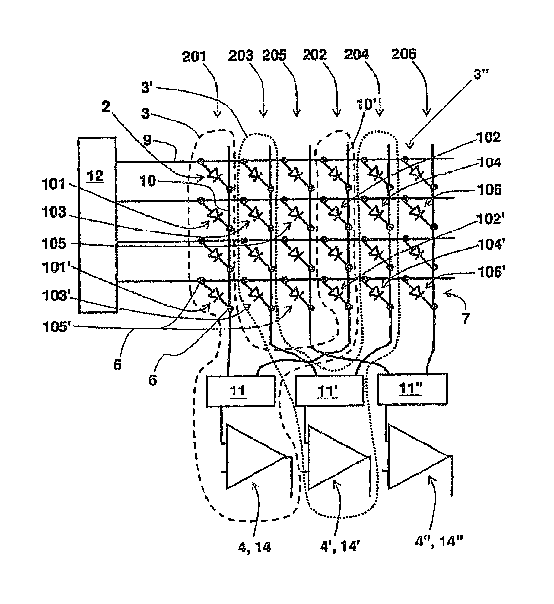
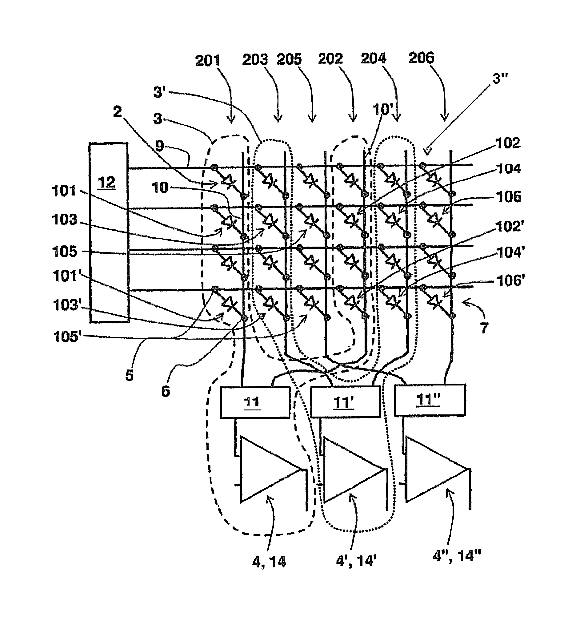
[0017]As shown in FIG. 1, a circuit configuration according to an exemplary embodiment of the present invention has four rows 7 of circuit elements 2, particularly diodes, each having first and second terminals 5, 6. One of rows 7 includes a first and a second sensor element 101, 102, which together are assigned to a first sensor-element block 3, a third and fourth sensor element 103, 104, which together are assigned to a second sensor-element block 3′, and a fifth and sixth sensor element 105, 106, which are assigned to a third sensor-element block 3″. Third and fifth sensor elements 103, 105 are situated between first and second sensor elements 101, 102, while second sensor element 102 is situated between fifth and fourth sensor elements 105, 104. Thus, the sensor-element blocks are interlaced in such a way that, disposed between at least two sensor elements of one sensor-element block is always at least one sensor element of at least one other sensor-element block.

[0018]Furthermo...


PUM


Abstract

A sensor system has a first sensor-element block and a second sensor-element block, at least one first sensor element and one second sensor element are assigned to the first sensor-element block, and at least one third sensor element is assigned to the second sensor-element block. The third sensor element is situated between the first and second sensor elements.

Description

BACKGROUND OF THE INVENTION[0001]1. Field of the Invention[0002]The present invention relates to a sensor system incorporating a plurality of sensor element blocks configured to be evaluated in parallel.[0003]2. Description of Related Art[0004]Sensor systems such as this are generally familiar. For example, published German Patent document 10 2006 028 435 describes a sensor for spatially resolved detection, the sensor including a substrate, a micro-patterned sensor element having an electrical property whose value changes as a function of temperature, particularly a diode, and a membrane disposed above a cavity in the substrate, and the sensor element being located on a bottom side of the membrane. The sensor elements include diode pixels, in particular able to be contacted via individual leads, a plurality of diode pixels preferably being configured in a diode-pixel array and being connected to shared leads via the individual leads, so that a sequential readout of the individual di...

Claims


Application Information

Patent Timeline
Patent Type & Authority Patents(United States)
IPC IPC(8): G01D7/00G06V30/144
CPCG06K9/00013G01D5/14G06K9/00973G06V10/94
Inventor HERRMANN, INGOREINHART, KARL-FRANZHERRMANN, DANIELFREUND, FRANK
Owner ROBERT BOSCH GMBH
Why Eureka
Try Eureka