Pipe-lining material and pipeline lining method

a technology of pipe-lining material and pipe-lining material, which is applied in the direction of shaft lining, shaft equipment, mechanical equipment, etc., can solve the problems of pipe-lining material becoming heavier, unable to draw, and difficult to insert into the pipeline, so as to reduce the lining work time, prevent damage to the lining, and facilitate and smoothly insert the pipeline

Inactive Publication Date: 2010-11-11
SHONAN GOSEI JUSHI SEISAKUSHO KK
View PDF17 Cites 21 Cited by
  • Summary
  • Abstract
  • Description
  • Claims
  • Application Information

AI Technical Summary

Benefits of technology

[0010]According to the present invention, the pipe-lining material is led and drawn into the pipeline by belt members each having elasticity and rigidity, so that the pipe-lining material can be easily and smoothly inserted into the pipeline even where there is a plurality of sections bent at a right angle or close to a right angle, and it is possible to prevent the pipe-lining material from being stretched and damaged by forcible insertion. This makes it possible to make the lining work time reduced.
[0011]Furthermore, the elastic and rigid belt members are attached to the sides of the pipe-lining material. This allows the pipe-lining material to be protected by the belt members during insertion, making it possible to prevent damage to the lining.

Problems solved by technology

However, in the conventional insertion method for a pipe-lining material, insertion into pipelines is extremely difficult in sections that are bent at a right angle or close to a right angle.
Furthermore, with a drawing-in method, the contact resistance of the pipe-lining material increases as the bent sections increase, and the pipe-lining material therefore becomes heavier and is unable to be drawn in.
If drawing-in continues forcibly, the pipe-lining material is stretched and damaged, which dramatically reduces the quality of the pipe-lining material.

Method used


Image

  • Pipe-lining material and pipeline lining method
  • Pipe-lining material and pipeline lining method
  • Pipe-lining material and pipeline lining method

Examples


Embodiment Construction

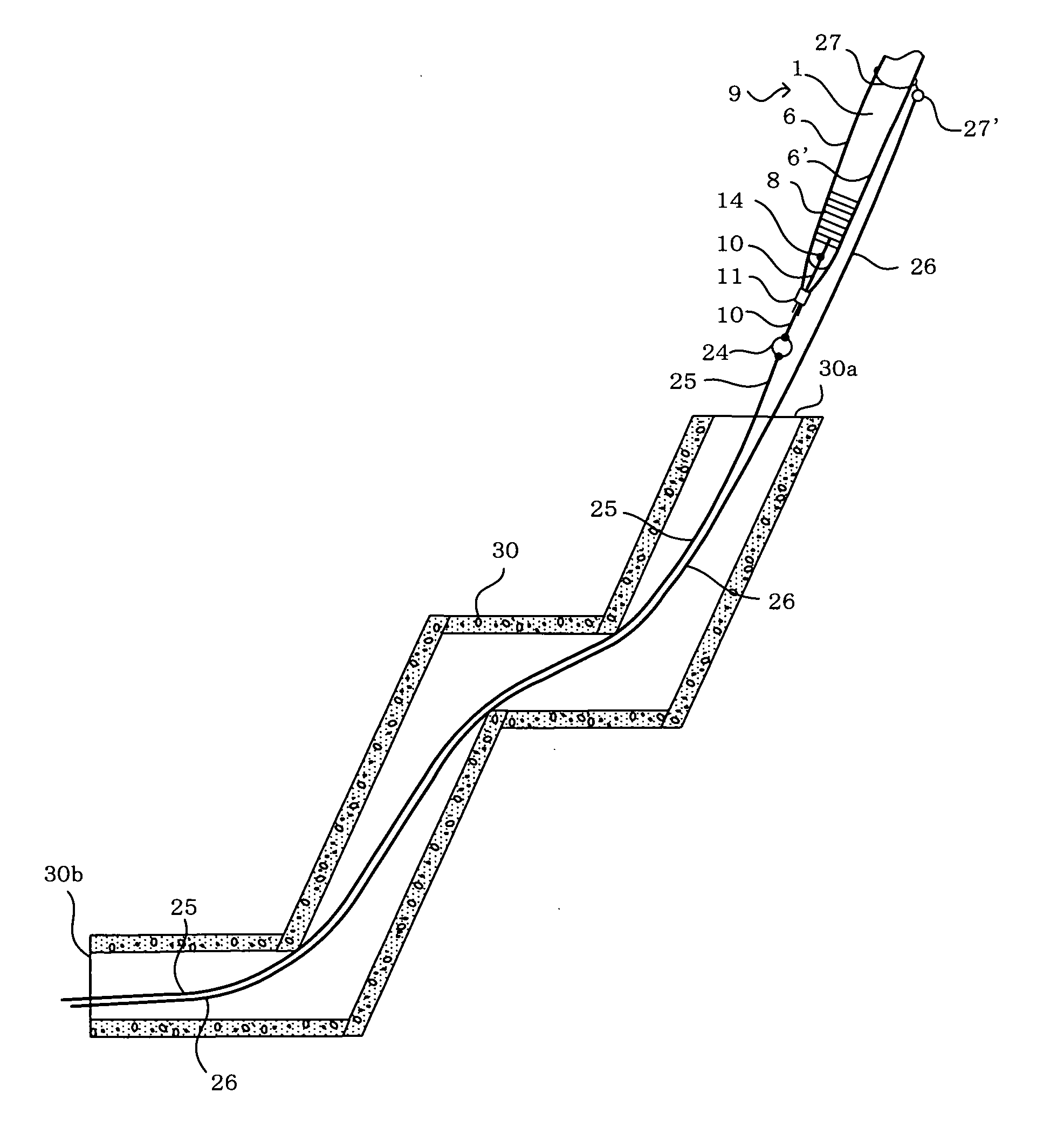
[0031]The present invention will now be described in detail with reference to the embodiments shown in the accompanying drawings. Described are pipelines such as sewers, communication conduits, gas lines, agricultural pipelines and the like each having a plurality of bent sections.

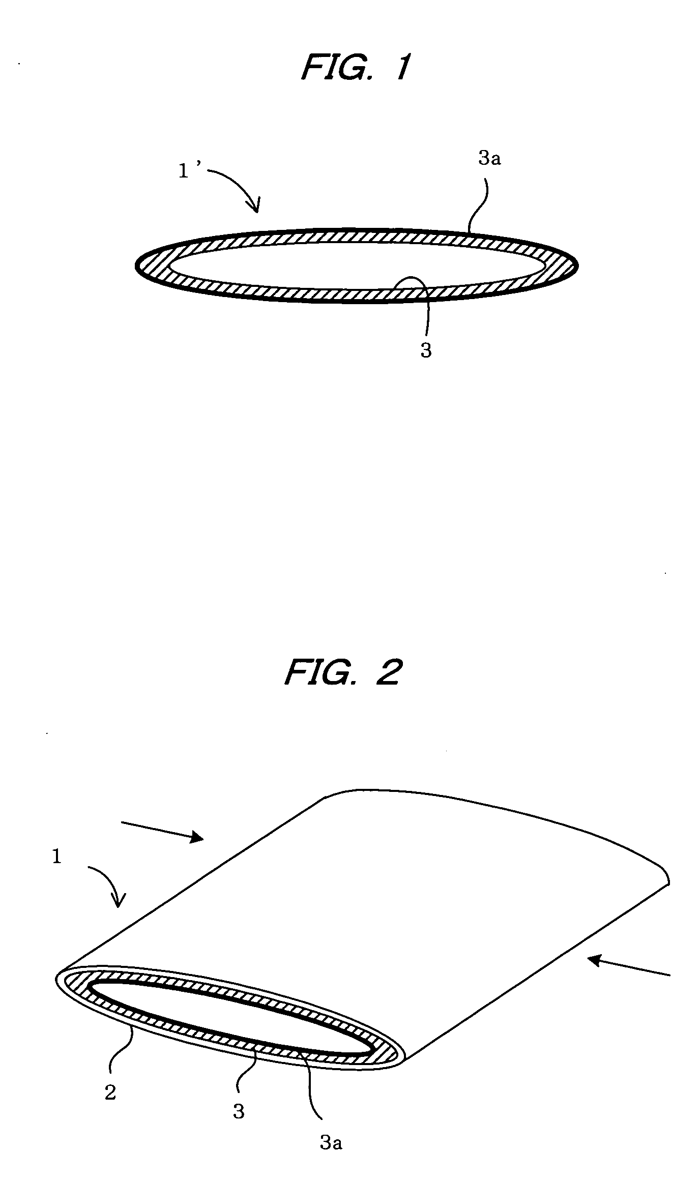
[0032]FIG. 1 shows a pipe-lining material used to repair pipelines. The pipe-lining material 1′ is a flexible tubular lining material comprising a flexible tubular resin-absorbing material 3 whose exterior surface is coated (heat-fused) with a highly airtight plastic film 3a of polyethylene, polypropylene, polyamide, vinyl chloride or the like.

[0033]The tubular resin-absorbing material 3 is composed of a non-woven or woven fabric or a mat made of plastic fiber of polyamide, polyester, polypropylene, or the like; a woven fabric or a mat made of glass fiber; or a non-woven or woven fabric or a mat that combines the use of the above-mentioned plastic fiber and glass fiber. The tubular resin-absorbing material...


PUM

PropertyMeasurementUnit
flexibleaaaaaaaaaa
elasticityaaaaaaaaaa
rigidityaaaaaaaaaa

Abstract

A flexible tubular pipe-lining material impregnated with a thermosetting resin is sandwiched by sandwiching steel belts in order to impart elasticity and rigidity thereto. A leading steel belt for leading the pipe-lining material is fixedly attached to the distal end thereof and the sandwiching steel belts. A drawing steel belt is removably attached to the leading steel belt to draw the pipe-lining material into a pipeline to be repaired. Additionally, an auxiliary steel belt is attached to the pipe-lining material to support the insertion thereof into the pipeline. The pipe-lining material can be inserted into the pipeline by the sandwiching steel belts, the drawing steel belt and the auxiliary steel belt. Such an arrangement allows the pipe-lining material to be easily and smoothly inserted into the pipeline even where there is a plurality of sections bent at a right angle or close to a right angle.

Description

BACKGROUND OF THE INVENTION[0001]1. Field of the Invention[0002]The present invention relates to a pipe-lining material used to line pipelines in order to repair an aged pipeline, and to a pipeline lining method using the same.[0003]2. Description of the Prior Art[0004]When a communications pipe, gas pipe, sewer pipe, water pipe, electrical pipe, or other pipeline buried under ground has aged, pipeline lining methods are carried out to repair a pipe in the pipeline without the pipe being removed from the ground. In such pipeline lining methods, a tubular pipe-lining material impregnated with a thermosetting resin is inserted into the pipeline by everting or drawing-in. The pipe-lining material is expanded by compressed air and pressed against an inner peripheral surface of the pipeline. In this sate, the pipe-lining material is heated to cure the thermosetting resin thereof in order to line the pipeline (e.g., Japanese Laid-open Patent Application No. 2006-123547).[0005]There are ty...

Claims


Application Information

Patent Timeline
Patent Type & Authority Applications(United States)
IPC IPC(8): F16L55/165F16L11/12
CPCF16L55/1656F16L55/1654
Inventor KAMIYAMA, TAKAOKANETA, KOJIFUJII, KENJITANAKA, FUMINORI
Owner SHONAN GOSEI JUSHI SEISAKUSHO KK
Why Eureka
Try Eureka