

Link of a side chain for conveyor belts
- Summary
- Abstract
- Description
- Claims
- Application Information
AI Technical Summary
Benefits of technology
Problems solved by technology
Method used
Image

Examples
first embodiment
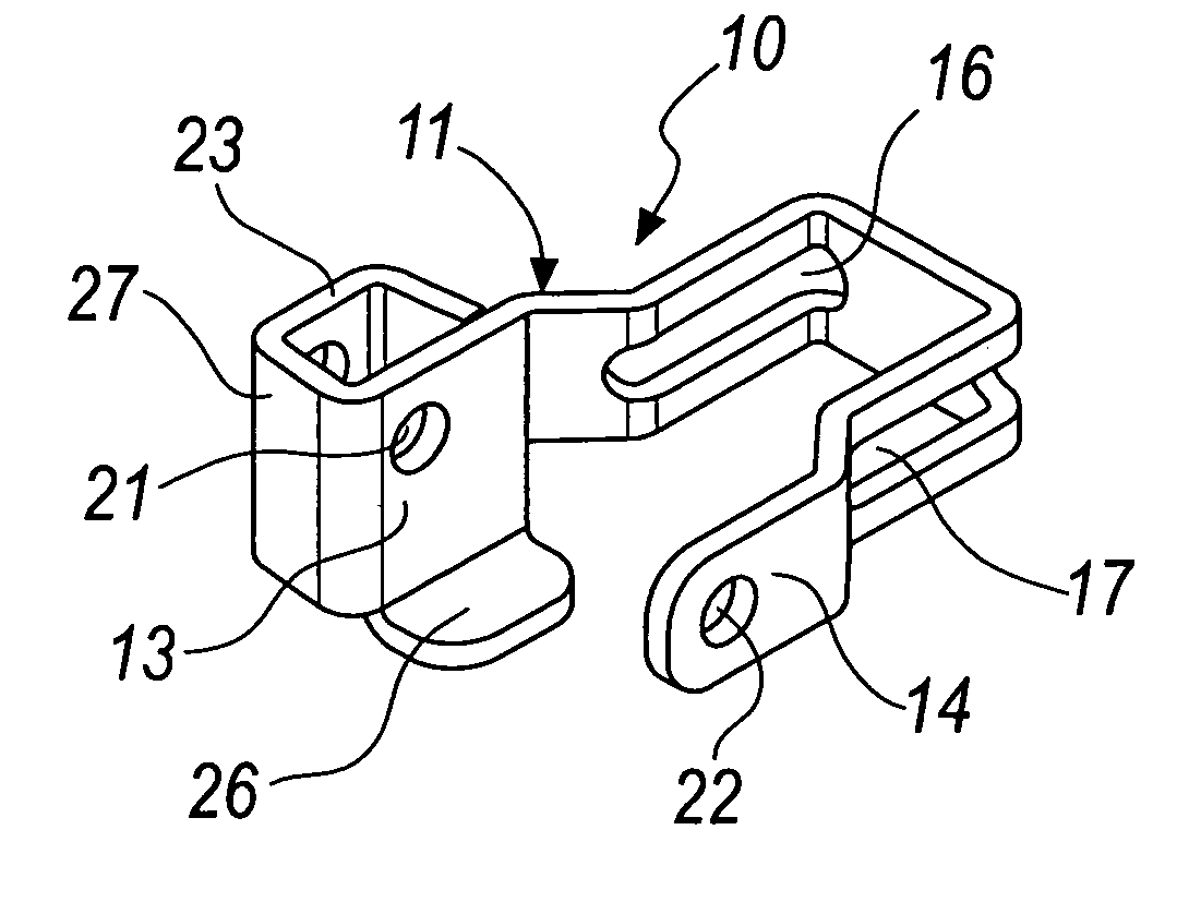
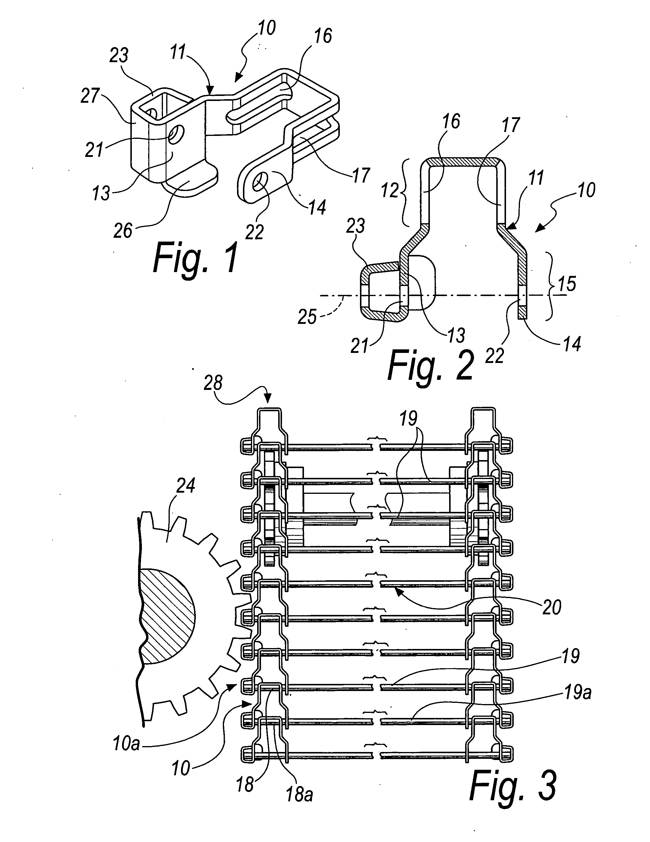
[0031]With reference to the figures, a link of a side chain for conveyor belts, particularly for food, is generally designated by the reference numeral 10 in its first embodiment, which is visible in FIGS. 1, 2 and 3.
[0032]The link 10 is of the type that comprises a substantially V-shaped body 11, with the front portion 12 shaped so as to fit between the two facing end parts 13 and 14 of the rear portion 15 of an identical link 10a arranged in front.
[0033]The front portion 12 has two longitudinally elongated symmetrical slots 16 and 17 for the passage and translational motion of an end portion 18 of a rod-like element 19 of a conveyor belt 20.
[0034]The rear portion 15 has, on each end part 13 and 14, a hole, respectively 21 and 22, for the insertion of an end portion 18a of an additional rod-like element 19a, as exemplified in FIG. 3.
[0035]The outer rear end part 13 has a lateral tab 23 that is contoured to mesh with a toothed wheel 24, but it might be a toothed belt, of associated ...
second embodiment
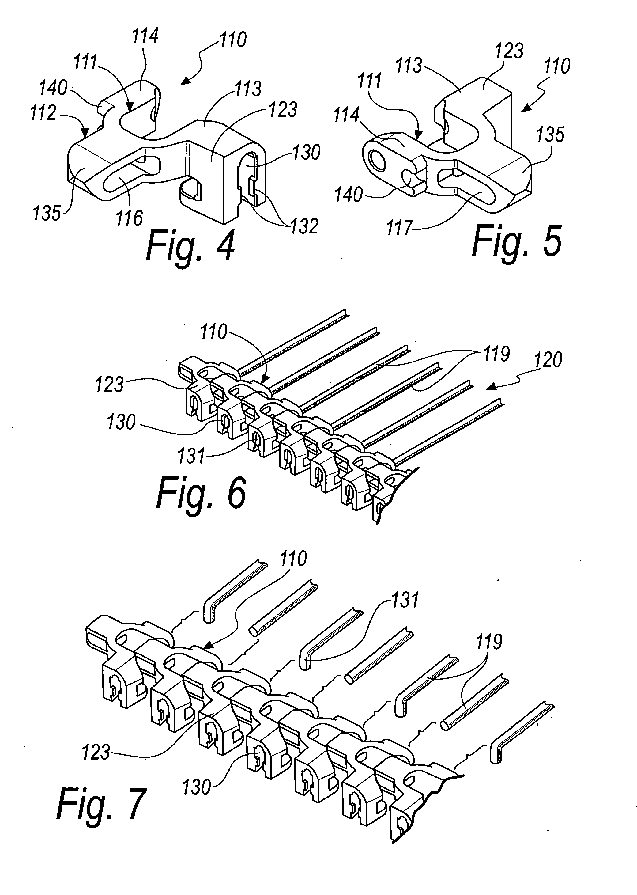
[0044]In its second embodiment, illustrated in particular in FIGS. 4 and 5 and designated therein by the reference numeral 110, the link 110 according to the invention is provided monolithically and made of plastics.
[0045]In the link 110, the lateral tab 123 extends toward the outside of the outer end part 113 and has a seat 130 for the rapid engagement of a complementarily shaped end 131 of a rod-like element 119 of the conveyor belt 120.
[0046]The seat 130 is open laterally onto the outside of the tab 123 and has protruding edges 132 for the snap engagement of the L-folded end 131 of a rod-like element 119.
[0047]The link 110 thus allows to provide a conveyor belt 120 with rod-like elements that have both ends 131 folded into an L-shaped configuration for engagement with the corresponding seats 130 on the lateral tabs 123, as shown in FIG. 6, or a similar conveyor belt whose rod-like elements 119 have a single L-folded end 131, as shown in FIG. 7, since it is sufficient in practice ...
third embodiment
[0048]In such third embodiment of FIG. 7, the belt 120 is much faster and cheaper to provide.
[0049]Further, by adopting chains composed of the links 110, it is also much simpler to join two pieces of conveyor belt 120 and the operation for closing the belt 120, without resorting to welding or other mechanical operations with the addition of mechanical elements, is also much easier and faster.
[0050]In the second embodiment of the link 110, which is monolithic and made of plastics, the front portion 112 has two slots 116 and 117, which are the lateral ports of a single through opening that is formed transversely to the front portion 112.
[0051]The tip 135 of the front portion 112 of the V-shaped body 111 has a profile shaped substantially like involutes of a circle, so as to better interact with the teeth 136 of a toothed wheel 137 for guiding the conveyor belt 120 upward, as shown in FIGS. 8 and 9, or downward.
[0052]The particular shaping of the V-shaped body 111 also allows to provid...
PUM
 Abstract
Description
Claims
Application Information