Logic Chip, Logic System and Method for Designing a Logic Chip

a logic chip and logic chip technology, applied in the field of logic chips, logic systems and methods for designing logic chips, can solve the problems of significant challenges in the complexity of logic circuits, logic chips and logic systems is steadily increasing, and the design of logic circuits is challenging. achieve the effect of avoiding interference between different resource blocks and facilitating circuitry

Active Publication Date: 2010-11-11
KOCH DIRK DR
View PDF6 Cites 52 Cited by
  • Summary
  • Abstract
  • Description
  • Claims
  • Application Information

AI Technical Summary

Benefits of technology

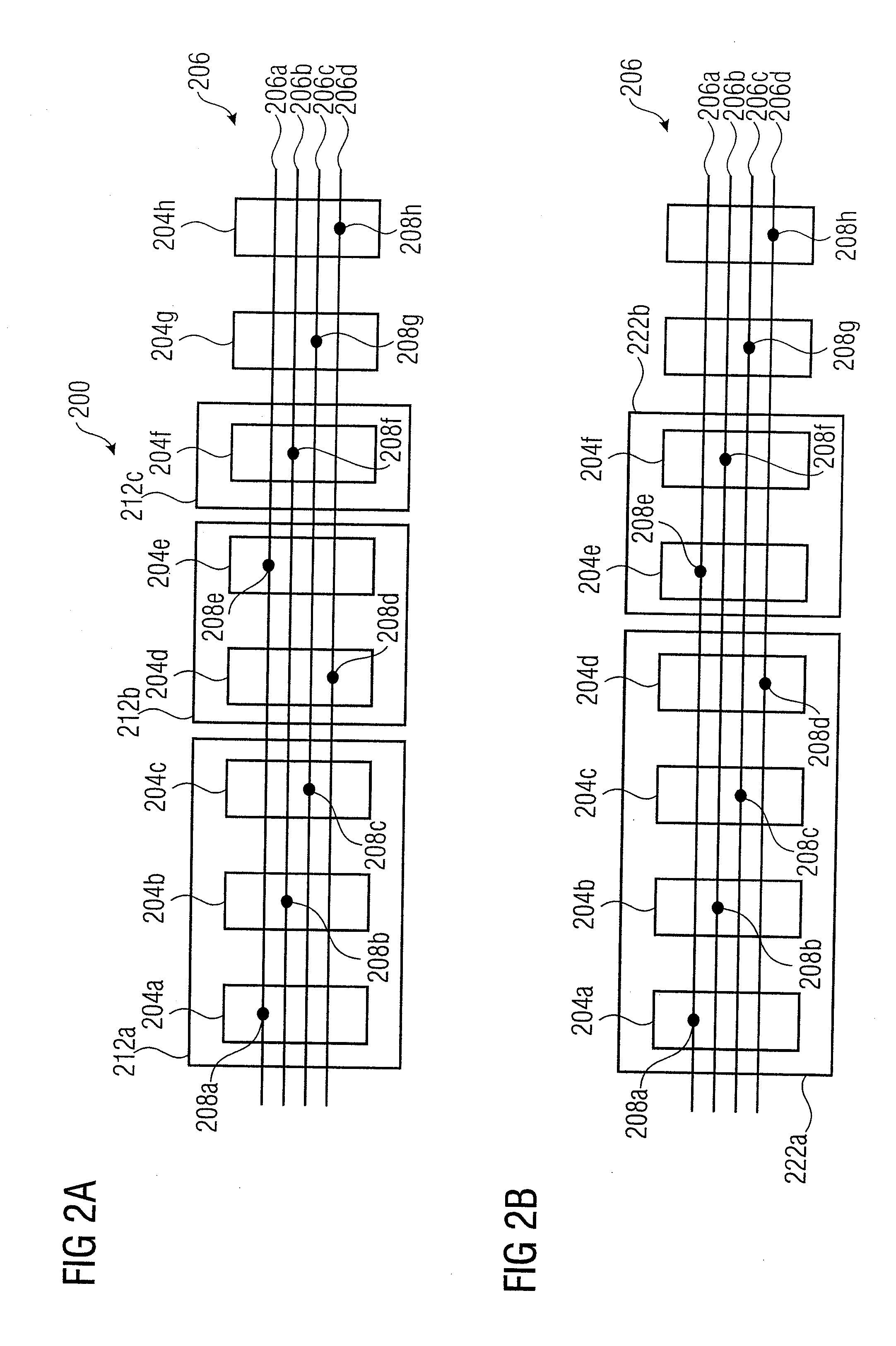
[0045]Some embodiments according to the invention are based on the finding that communication on a logic chip, the chip comprising a plurality of individually addressable resource blocks, can be established in an efficient way by using a communication bar concept, wherein a communication bar extends across a plurality of individually addressable resource blocks, wherein interface locations of the communication bar remain constant across a plurality of the resource blocks, wherein one or more of the resource blocks contribute a bypass-segment to the communication bar, and wherein one or more of the resource blocks contribute an access segment to the communication bar. Accordingly, a flexible configuration is possible, in that it can be decided flexibly which of the resource blocks are coupled to the communication bar and which are not coupled to the communication bar. Also, the uniform structure of the communication bar, uniform across multiple resource blocks, allows for a flexible modification of the sequence of the resource blocks. For example, a sequence of resource blocks comprising only bypass segments of the communication bar can be exchanged flexibly in some embodiments. However, in some cases there may be some restrictions with respect to the position (or order) of resource blocks comprising access segments.
[0065]In some embodiments, the one or more channels of the communication bar may be unidirectional channels. This may facilitate the circuitry and may also allow for a read / modify / write type of forwarding of the signals. Further a fixed upstream-to-downstream relationship is defined in this way.
[0066]In some embodiments, one of the one or more channels of the communication bar may be a dedicated channel for a connection of a single one of the individually addressable resource blocks with an input terminal of the logic chip, or with an output terminal of the logic chip. Accordingly, the single one of the resource blocks of the logic chip may comprise an access segment for an access to the dedicated channel of the communication bar. All the other resource blocks of the logic chip may comprise bypass segments with respect to the dedicated channel. Accordingly, only a single one of the resource blocks of the logic chip has access to the dedicated channel, while the other resource blocks behave neutrally by providing bypass segments for the dedicated channel. Accordingly, an interference between different resource blocks is avoided by the physical structure of the communication bar.
[0067]In some embodiments, the logic chip may be a field programmable gate array. Accordingly, a flexible exchange of the resource blocks may be possible, thus allowing for different arrangements of the resource blocks with respect to each other.
[0076]The above described logic system allows for a flexible configuration. For example, the structure of the communication bar allows for a flexible allocation of the block configurations to the resource blocks. Functionally substantially identical communication bar structures are obtained in different allocations of the block configurations to the resource blocks (or to block positions). Complete configurations of the resource blocks may be stored in the configuration repository and the configurations do not need to be changed when allocating the block configuration to resource blocks (or to a block positions). Thus, a configuration of a resource block (with respect to the bypassing or accessing of the communication bar) is not necessitated after allocating a configuration to a resource block (or to a block position).
[0080]Accordingly, a maximum flexibility regarding an allocation of block configurations to different resource block positions is achieved.

Problems solved by technology

The design of logic circuits has been a challenging task.
However, at present, the complexity of logic circuits, logic chips and logic systems is steadily increasing.
This brings along significant challenges in the design of such logic circuits.
Also, with increasing complexity of the logic circuits, it is getting more and more difficult to provide an efficient way of interconnecting different logic blocks.
One important issue of this work is the interfacing of hardware accelerators to on-chip buses (OCBs) and to the static system containing typically a CPU, the memory, and the I / O interface modules.
This approach does not allow a direct connection to I / O-peripherals connected to the OCB.
Both approaches do not allow a module to directly access any memory of the system.
The large multiplexers have also significant propagation delays leading to decreased throughputs when using circuit switching.
This approach necessitates a significant amount of area on the FPGA around the modules in order to build the routing because there is no technique available to share the routing wires inside the templates for building multiple routing tracks.
As modules are obstacles for this kind of routing, the area necessitated for routing cannot be used to implement the module's logic.
We can conclude that packet routing produces an enormous overhead when implemented on FPGAs.
However, newer FPGA architectures have no support for tristate wires and none of these approaches deal efficiently with dedicated signals, e.g., interrupt lines and chip select signals.
The main drawback of this solution is that all modules have to fit into such a resource area and that the resource areas could not be shared by multiple modules, even if the logic of multiple modules would fit into the same resource area.
However, in some cases there may be some restrictions with respect to the position (or order) of resource blocks comprising access segments.
Also, some of the channels may serve as place holders, and may remain unused in some configurations of the logic chip.

Method used


Image

  • Logic Chip, Logic System and Method for Designing a Logic Chip
  • Logic Chip, Logic System and Method for Designing a Logic Chip
  • Logic Chip, Logic System and Method for Designing a Logic Chip

Examples


Embodiment Construction

[0148]Embodiments according to the invention will subsequently be described taking reference to the enclosed Figs.

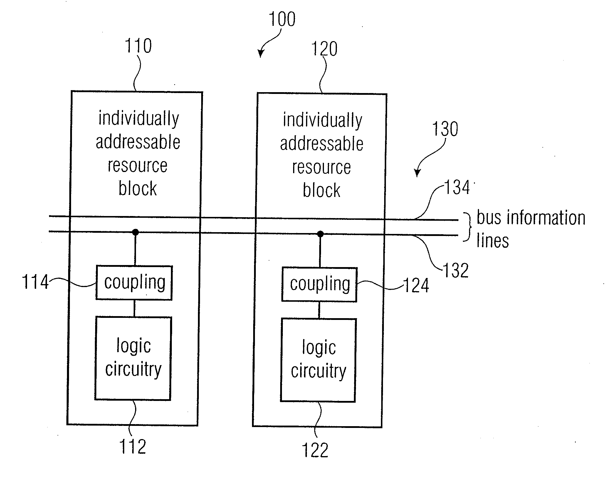
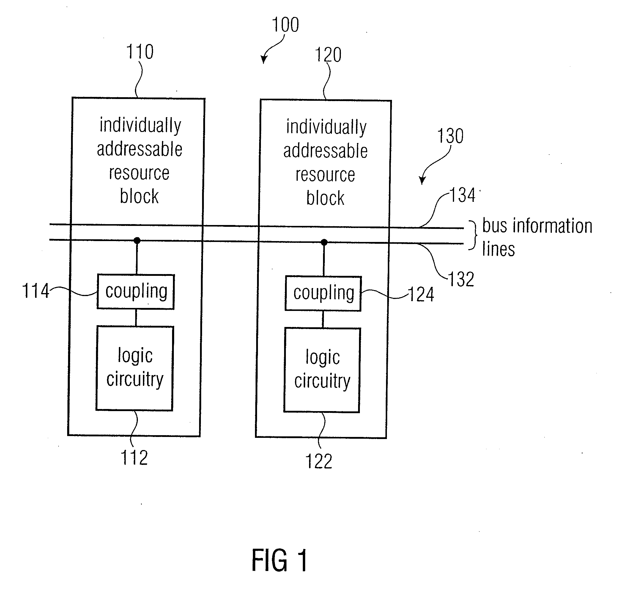
[0149]FIG. 1 shows a block schematic diagram of a logic chip, according to an embodiment of the invention. The logic chip is designed in its entirety with 100. The logic chip comprises a plurality of individually-addressable resource blocks (or resource slots), for example, a first individually-addressable resource block 110 and a second individually-addressable resource block 120. Each of the individually-addressable resource blocks comprises logic circuitry 112, 122.

[0150]It should be noted that the individually-addressable resource blocks may, for example, be individually-addressable resource slots. Alternatively, the individually-addressable resource blocks may be modules, wherein a module may comprise a plurality of resource slots. However, a mixed configuration may be used, wherein the first individually-addressable resource block may be an individually-addressable...


PUM


Abstract

A logic chip has a plurality of individually addressable resource blocks each of the resource blocks having logic circuitry, and a communication bar extending across a plurality of the individually addressable resource blocks. The communication bar has a plurality of communication bar segments associated with the resource slots. The communication bar segments of the individually addressable resource blocks have identical interface locations with respect to boundaries of the resource blocks, such that an input interface location of a first resource block matches an output interface location of an adjacent second resource block. At least one of the individually addressable resource blocks has a bypass segment of the communication bar. At least one of the individually addressable resource blocks has an access segment of the communication bar. The access segment has an access structure inserted between a first communication bar interface location and a second communication bar interface location, to allow for a read access or a write access or a combined read / write access to the communication bar.

Description

CROSS-REFERENCE TO RELATED APPLICATIONS[0001]This application is a National Phase of PCT / EP2008 / 007342 filed 8 Sep. 2008, which claims priority from German Patent Application No. 07017975.9, which was filed on 13 Sep. 2007, and is incorporated herein in its entirety by reference.BACKGROUND OF THE INVENTION[0002]Some embodiments according to the invention are related to a logic chip and to a method and computer program for providing a configuration information for a configurable logic chip.[0003]Some embodiments according to the invention are related to a logic chip, a logic system and a method and computer program for designing a logic chip.[0004]Some embodiments according to the invention are related to efficient re-configurable on-chip buses.[0005]Some embodiments according to the invention are related to further developments regarding efficient re-configurable on-chip buses.[0006]Some embodiments according to the invention are related to efficient re-configurable on-chip buses fo...

Claims


Application Information

Patent Timeline
Patent Type & Authority Applications(United States)
IPC IPC(8): H03K19/177G06F17/50
CPCG06F15/7867G06F15/8015H03K19/17796H03K19/17736H03K19/17748G06F17/5054G06F30/34
Inventor KOCH, DIRKSTREICHERT, THILOHAUBELT, CHRISTIANTEICH, JUERGEN
Owner KOCH DIRK DR
Why Eureka
Try Eureka