Systems and methods for establishing peer-to-peer communications between network devices communicating via a common bus

Active Publication Date: 2006-07-25
THE BOEING CO
View PDF32 Cites 31 Cited by
  • Summary
  • Abstract
  • Description
  • Claims
  • Application Information

AI Technical Summary

Benefits of technology

[0016]A method of establishing peer-to-peer communications is also provided. The systems and methods of various embodiments of the present invention therefore allow source devices and receiving devices to establish peer-to-peer communications via a common network bus without dedicated wiring. Additionally, the systems and methods of various embodiments of the present inv

Problems solved by technology

As systems have become more integrated and the communications requirements have been increased, the amount of dedicated wiring that would be required has become excessively large, both in terms of the space required for the wiring and the cost of the wiring and the attendant installation.
Moreover, as the amount of dedicated wiring increases, the overall complexity of the system also generally increases, as well as the likelihood that some portion of the wiring might be damaged or broken during or following installation.
Unfortunately, analog signals are susceptible to noise introduced into the signals during data transmission.
Given that many of the transmitted signals have a low amplitude to start with, this noise can corrupt the signal and decrease the signal to noise ratio to levels that cause loss of resolution in the signal.
Further, as many of these network devices are scattered some distance from the controller, the electrical lines connecting the network devices to the controller may be sufficiently long to cause signal degradation due to DC resistance in the wiring.
But, many conventional digital networks suffer from a variety of problems themselves.
For example, many existing digital networks operate according to complicated protocols which require each network device to have a relatively high level processor, ther

Method used


Image

  • Systems and methods for establishing peer-to-peer communications between network devices communicating via a common bus
  • Systems and methods for establishing peer-to-peer communications between network devices communicating via a common bus
  • Systems and methods for establishing peer-to-peer communications between network devices communicating via a common bus

Examples


Example

[0023]The present invention now will be described more fully hereinafter with reference to the accompanying drawings, in which preferred embodiments of the invention are shown. This invention may, however, be embodied in many different forms and should not be construed as limited to the embodiments set forth herein; rather, these embodiments are provided so that this disclosure will be thorough and complete, and will fully convey the scope of the invention to those skilled in the art. Like numbers refer to like elements throughout.

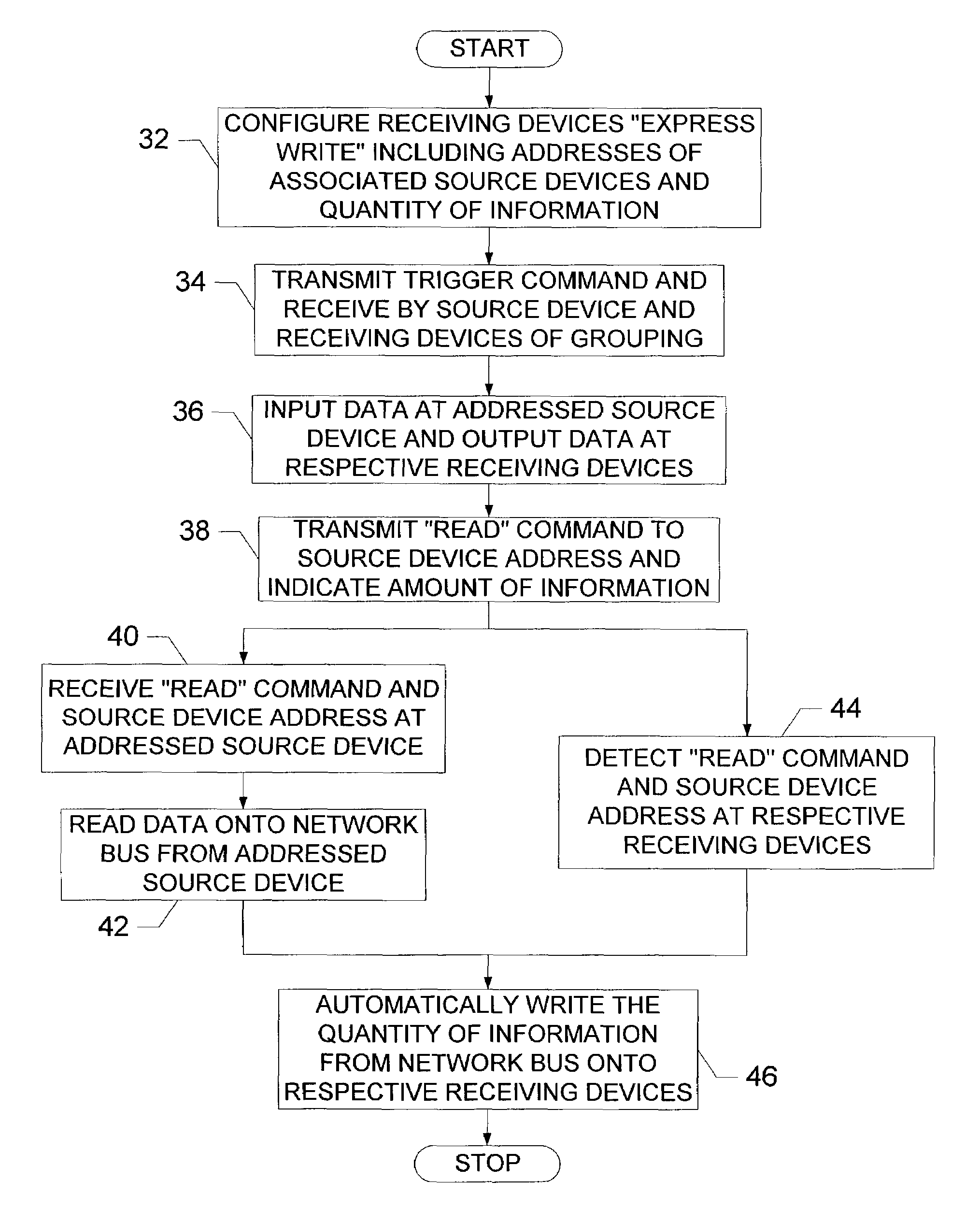
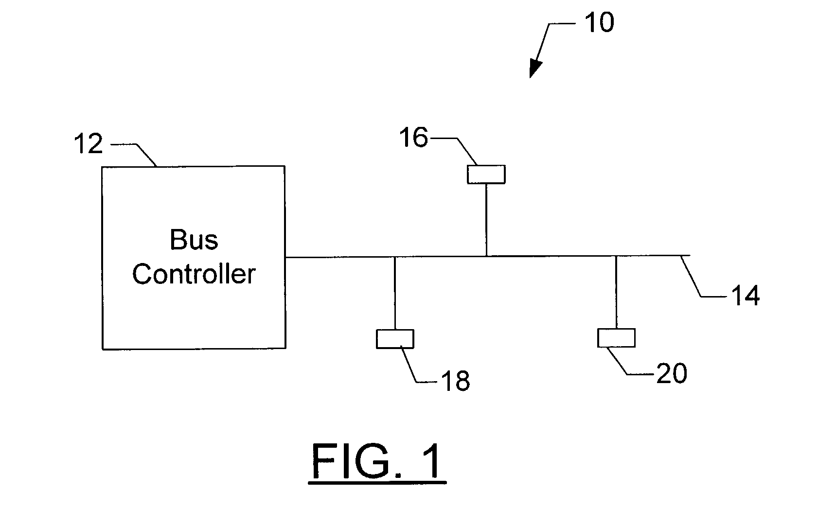
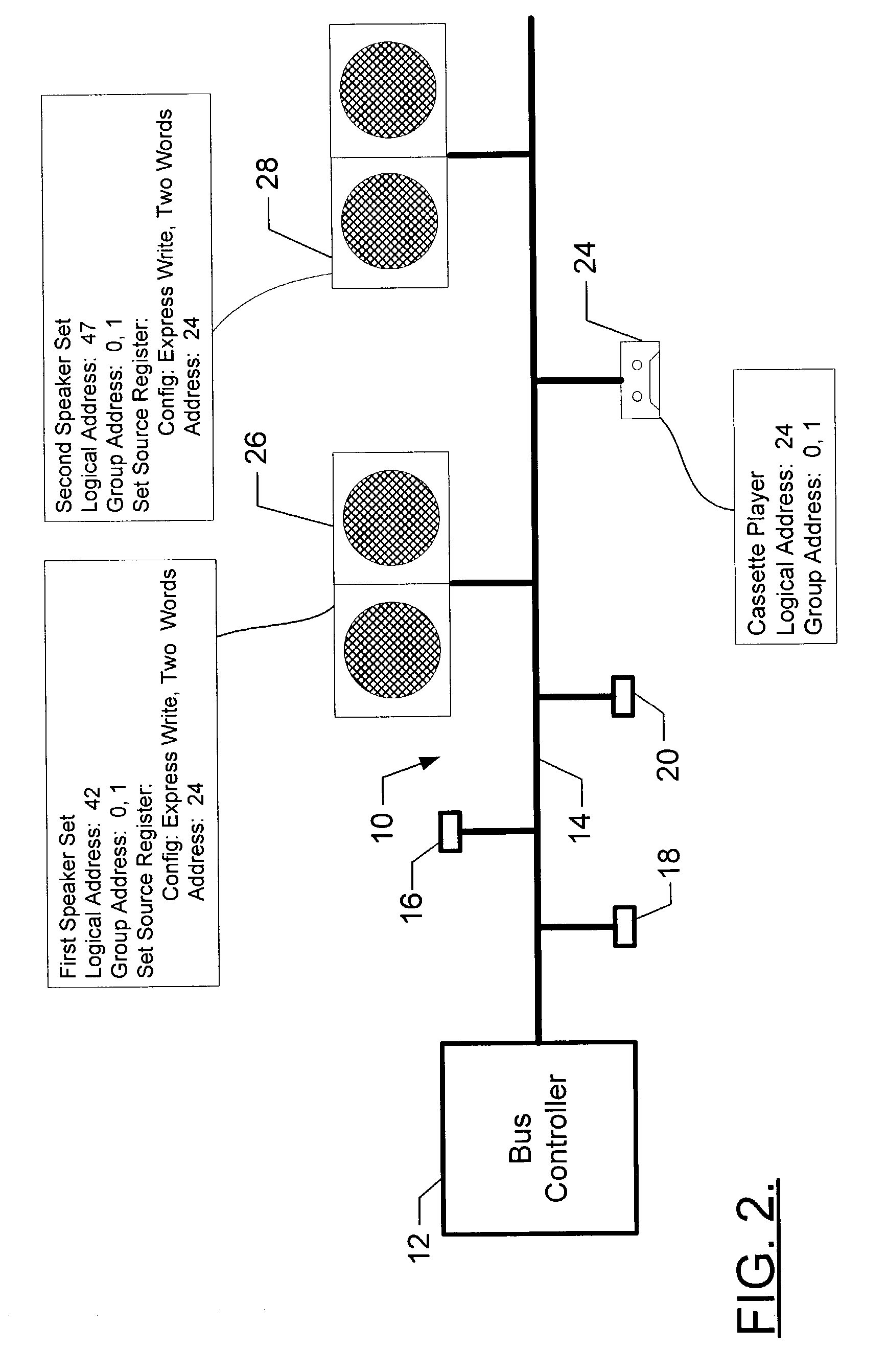
[0024]As discussed briefly above and in greater detail below, the present invention provides systems and methods for establishing peer-to-peer communications in a network system. Importantly, the systems and methods of the present invention configure at least one group of network devices that are connected to the network bus to at least partially communicate without interdiction from the bus controller to thereby permit more efficient communication, such a...


PUM


Abstract

A system for establishing peer-to-peer communications via a network bus comprises a bus controller and at least one peer-to-peer grouping including a source device and at least one receiving device, all of which are in electrical communication with the network bus. The bus controller controls communications on the network bus and can transmit onto the network bus an express command, which is associated with the source device of one of the groupings and identifies data on the respective source device. The source device of a respective grouping is capable of receiving a transmitted express command, and the receiving devices of the respective grouping are capable of detecting the transmitted express command. Upon receipt, the source device is capable reading the data identified by the respective express command onto the network bus, and thereafter the receiving devices of the respective grouping are capable of automatically writing data from the network bus.

Description

FIELD OF THE INVENTION[0001]The present invention relates generally to controlling communication on a network bus and, more particularly, to establishing peer-to-peer communication between network devices communicating via a common bus.BACKGROUND OF THE INVENTION[0002]As systems, such as the multimedia entertainment, communications, process control, and diagnostic systems utilized by the automotive and aerospace industries, become more complex, a need arises for additional devices to communicate, either with each other or with a central controller or the like. Historically, these systems included dedicated wiring extending between the various devices in order to support communications therebetween. As systems have become more integrated and the communications requirements have been increased, the amount of dedicated wiring that would be required has become excessively large, both in terms of the space required for the wiring and the cost of the wiring and the attendant installation....

Claims


Application Information

Patent Timeline
IPC IPC(8): G06F13/00H04L12/403H04L29/06H04L29/08
CPCH04L12/403H04L12/417H04L69/329H04L65/4084H04L12/40013H04L2012/40267H04L29/06027H04L65/612H04L65/1101
Inventor ELLERBROCK, PHILIP JOHNGRANT, ROBERT LEEMANKONZ, DANIEL WILLIAMWINKELMANN, JR., JOSEPH P.
Owner THE BOEING CO
Why Eureka
Try Eureka