Capacitive touch panel structure with high optical uniformity

a touch panel and optical uniformity technology, applied in the field of touch panel, can solve the problem that the electronic pattern cannot be recognized by human eyes, and achieve the effect of clear outward appearance, high optical uniformity structure and higher transmission

Inactive Publication Date: 2010-11-11
HANNSTOUCH SOLUTION
View PDF9 Cites 54 Cited by
  • Summary
  • Abstract
  • Description
  • Claims
  • Application Information

AI Technical Summary

Benefits of technology

[0011]One advantage of the present invention provides users capacitive touch panels with clear outward appearance because of its high optical uniformity structure. Therefore, the electrode pattern can not be recognized by human eyes.
[0012]The other advantage of the present invention is to provide a capacitive touch panel structure with higher transmission and better reliability.
[0013]Another advantage of the present inventi

Problems solved by technology

Therefore, the electrode pattern c

Method used


Image

  • Capacitive touch panel structure with high optical uniformity
  • Capacitive touch panel structure with high optical uniformity
  • Capacitive touch panel structure with high optical uniformity

Examples


Embodiment Construction

[0023]The invention will now be described in greater detail with preferred embodiments and illustrations attached. Nevertheless, it should be recognized that the preferred embodiments of the invention are only for illustrating. Besides the preferred embodiments mentioned here, this present invention can be practiced in a wide range of other embodiments besides those explicitly described, and the scope of the present invention is expressly not limited expect as specified in the accompanying Claims.

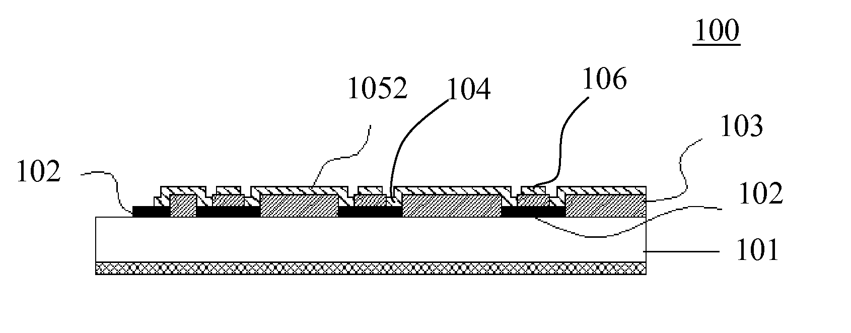
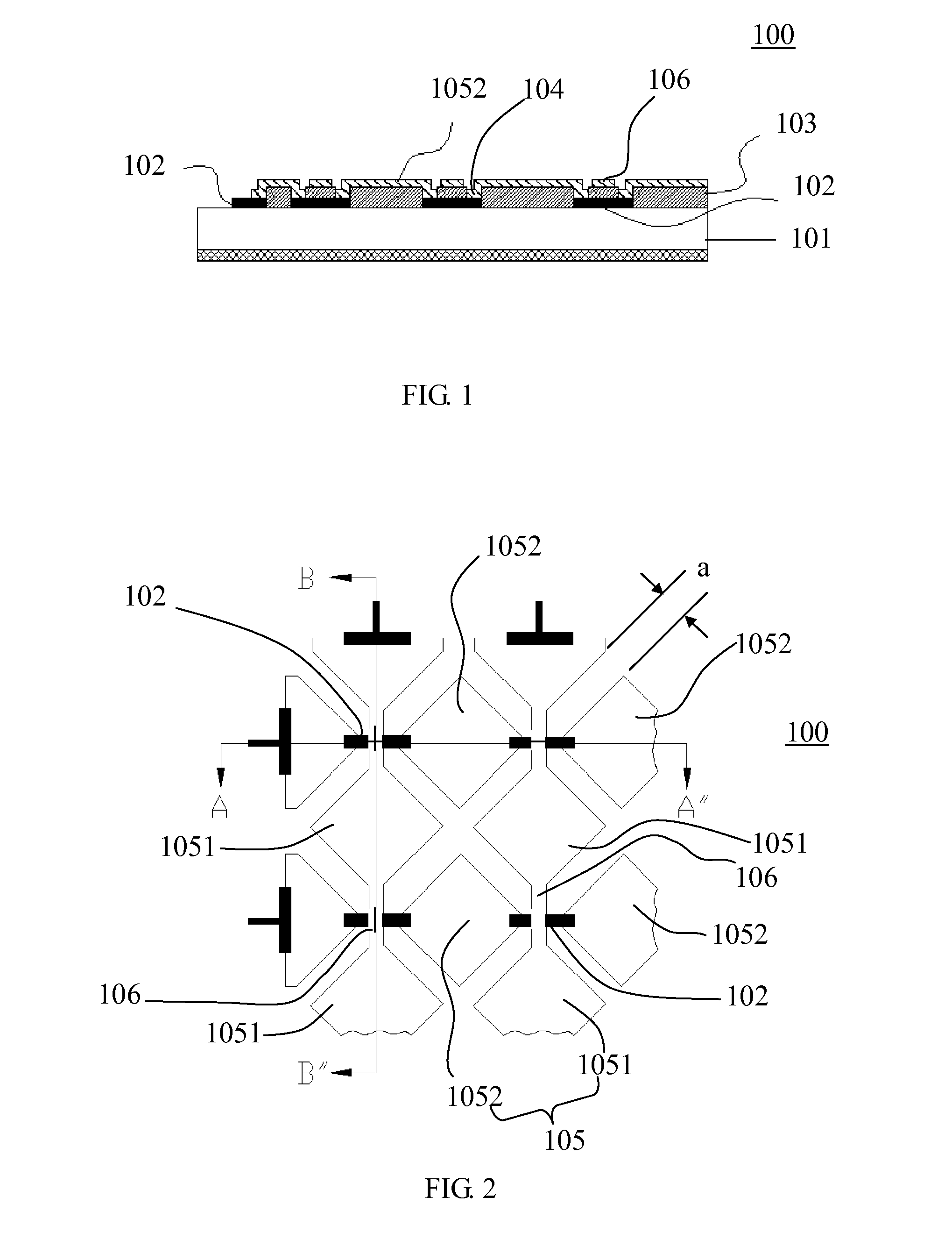
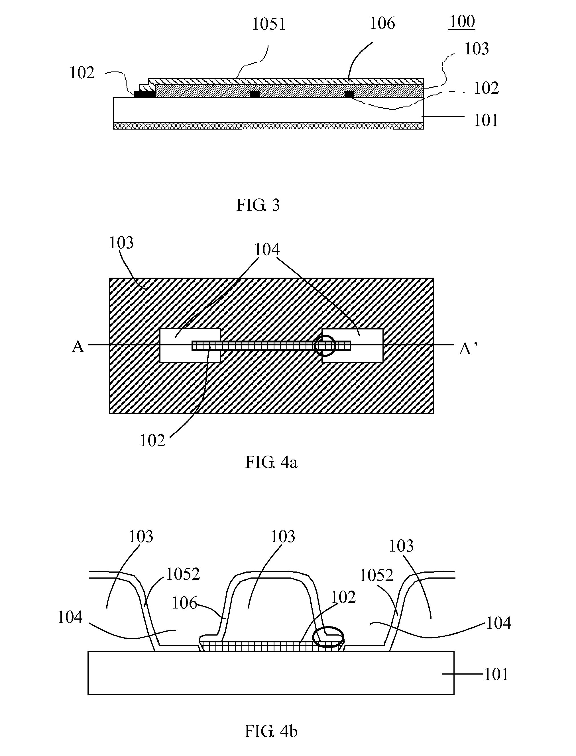
[0024]For one of the touch panel structure in prior art, the insulating layer covers part of the metal bridge pattern, after a high temperature process, for example high temperature indium-tin-oxide (ITO) layer sputtering deposition, the edge of insulating pattern will contract and form a cavity between the insulating pattern and ITO layer. The situation will get worse in the island-like insulating patterns and will reduce yield and reliability. In the present invention, the insulating laye...


PUM


Abstract

A capacitive touch panel structure with high optical uniformity includes a substrate, a metal layer, an insulating layer and an electrode layer. The metal layer is formed on surface of the substrate to constitute a plurality of metal bridge patterns and a plurality of traces. The insulating layer is coated on the surfaces of the substrate, and a plurality of via holes are formed on partial surface of the metal bridge patterns. A first direction electrode pattern, without electrically connected with the metal bridge patterns, is formed on the surface of the insulating layer between the metal bridge patterns. A second direction electrode pattern covers over the partial metal bridge patterns and into the via holes.

Description

BACKGROUND OF THE INVENTION[0001]1. Field of the Invention[0002]The present invention relates to a touch panel, and more particularly to a capacitive touch panel structure with high optical uniformity.[0003]2. Description of the Prior Art[0004]Touch panels can be produced in a variety of types and sizes without mouse, button or direction key and can be used as input part of a wide variety of electronic devices. With information appliance developing, the touch panels have replaced keyboard and mouse to communicate with the information appliance. The touch panels provide users a friendly interface such that operations of computers or electronic products become simple, straightforward, lively and interesting. Depending on fields of applications, touch panels are applied to portable communication and information products (for example, personal digital assistant (PDA)), financial / commercial system, medical registration system, monitoring system, information guiding system, and computer-a...

Claims


Application Information

Patent Timeline
IPC IPC(8): G06F3/045
CPCG06F2203/04111G06F3/044G06F3/0446G06F3/0443
Inventor WU, KUN-LONGLIU, YU-WEI
Owner HANNSTOUCH SOLUTION
Why Eureka
Try Eureka