Lens member and optical unit using said lens member

a technology of lens member and optical unit, which is applied in the direction of instruments, lighting and heating apparatus, semiconductor devices for light sources, etc., can solve the problems of loss of light passing through this portion, difficult to maximize the light utilization efficiency, and loss of light generated by this portion, etc., to achieve excellent appearance and high light utilization efficiency. effect of light emitted from the light sour

Active Publication Date: 2010-11-11
CITIZEN WATCH CO LTD +1
View PDF2 Cites 66 Cited by
  • Summary
  • Abstract
  • Description
  • Claims
  • Application Information

AI Technical Summary

Benefits of technology

[0020]Since the optical unit of the present invention has the optical axis of the light source disposed coaxially with the central axis of the light source-facing surface, the usage efficiency of light emitted from the light source

Problems solved by technology

However, the above-mentioned conventional technology leaves the following problems.
That is, the lenses disclosed in JP 57-55002 A, JP 59-119340 A, and JP 05-281402 A have the disadvantage that a loss is generated due to a part of the entering light not reaching the reflecting surface, making it difficult to maximize usage efficiency of the light.
For example, in JP 05-281402 A, there is a portion between the light-entrance surface and the refractive lens portion where the entering light does not reach the reflecting surface, resulting in loss of the light passing through this portion.
As a result, even if this TIR lens 1 is turned into a Fresnel lens, if a co

Method used


Image

  • Lens member and optical unit using said lens member
  • Lens member and optical unit using said lens member
  • Lens member and optical unit using said lens member

Examples


first embodiment

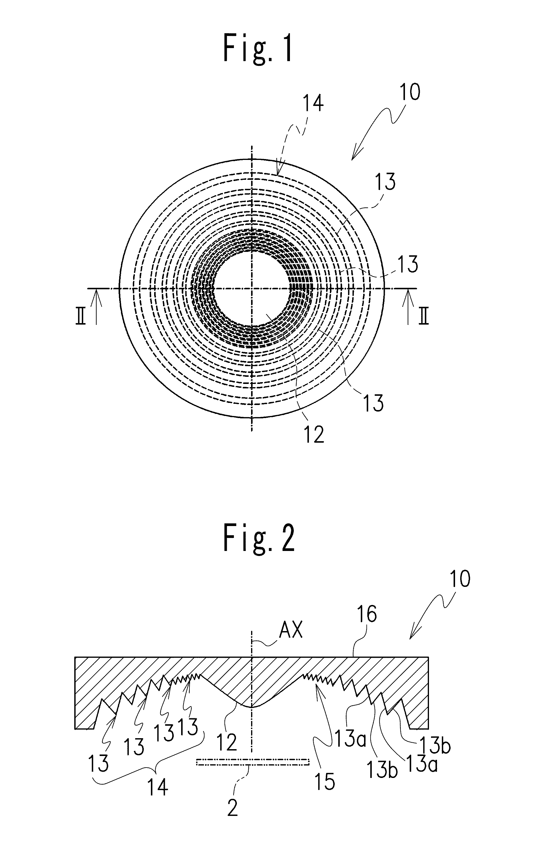
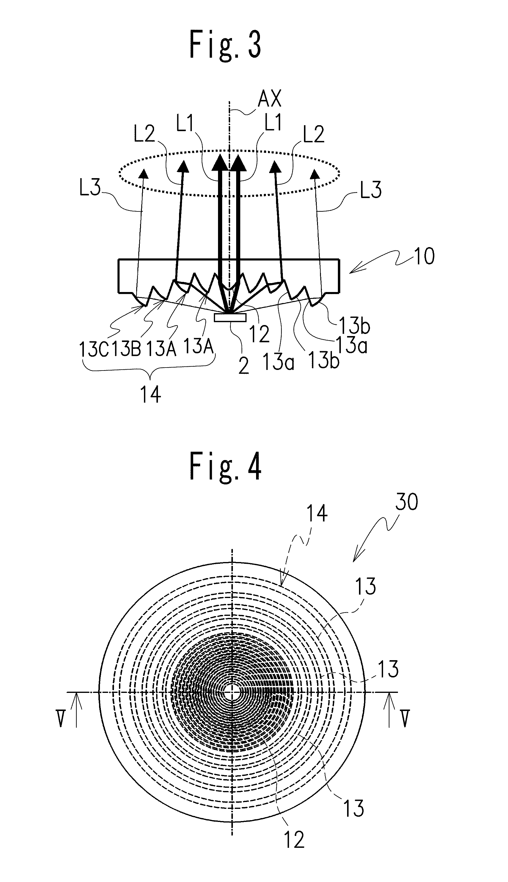
[0061]FIGS. 1-3 show a lens member 10 in accordance with the present invention. Note that the scale in the various drawings used for the following description is suitably altered to render the various members of a discernible size.

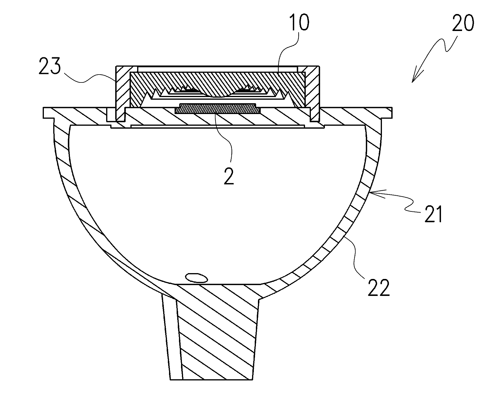
[0062]A plate-shaped lens member 10 has a plurality of concentric annular prisms each including an inner annular surface divided from a light-entrance surface 3 of a conventional TIR lens 1 shown in FIG. 29 and an outer annular surface divided from a light-reflection surface 4 of the conventional TIR lens 1 in which the light-entrance surface 3 has a concave shape provided in a lower portion of the conventional TIR lens 1 and the light-reflection surface has a convex shape positioned at a peripheral side of the conventional TIR lens 1 to surround the light-entrance surface. The light-entrance surface being disposed to face a light source 2 that uses an LED with a central axis of the light-entrance surface and a central axis of the light source corresponded...

second embodiment

[0090]Next, chromaticity of illuminating light after being passed through the plate-shaped lens member 30 of the second embodiment is investigated. Results are shown in FIG. 12. In addition, for comparison, color variability is similarly investigated also for a comparison-purpose lens member 100 having a convex lens portion 101 integrally formed in a central portion of the light-entrance surface, as shown in FIG. 13. Results are shown in FIG. 14. Note that the color variability images shown in FIGS. 12 and 14 are color images converted to grayscale black-and-white images.

[0091]On comparison, it is found that, whereas in the lens member 100 used for purposes of comparison there is color variability with locally occurring yellowish regions and bluish regions, in the lens member 30 of the second embodiment color variability is reduced overall with few yellowish or bluish regions.

[0092]Note that the even if light source 2, which may have a plurality of blue LED elements arranged therein...

third embodiment

[0095]As shown in FIG. 16, the irregularities in this third embodiment are a plurality of elliptically-shaped convex portions 41 arranged on the light-exit surface 16, the convex portions having diffusion capability for diffusing emitted light. Note that the convex portions 41 preferably have a non-spherical surface in order to efficiently refract light. Moreover, the convex portions may also have a quadrangular pyramid shape, for example.

[0096]In FIG. 17, color variability of the lens member 40 in accordance with the third embodiment is investigated. This image shows color variability to be further reduced compared to the lens member 30 of the second embodiment.

[0097]Having the convex portions 41 for controlling at least one of diffusion capability and directivity of the emitted light formed on the light-exit surface 16 opposite to the Fresnel lens surface 14 in the lens member 40 of the third embodiment in this way makes it easy to emit light focused as much as possible by the Fre...


PUM


Abstract

A plate-shaped lens member has concentric annular prisms each including an inner annular surface divided from a light-entrance surface of a conventional TIR lens and an outer annular surface divided from a light-reflection surface of the TIR lens in which the light-entrance surface has a concave shape provided in a lower portion of the TIR lens and the light-reflection surface has a convex shape positioned at a peripheral side of the TIR lens to surround the light-entrance surface. The light-entrance surface and light-reflection surface of the bulky TIR lens are Fresnel-ized or divided into a set of concentric annular prisms on a surface of the plate-shaped lens member and positions of divided portions from the TIR lens are efficiently arranged on the surface of the plate-shaped lens member.

Description

CROSS-REFERENCE TO THE RELATED APPLICATION[0001]The application is based on and claims the priority benefit of Japanese Patent Applications No. 2009-114065, filed on May 5, 2009 and No. 2010-002291, filed on Jan. 7, 2010, the entire descriptions of which are incorporated herein by reference.BACKGROUND OF THE INVENTION[0002]1. Field of the Invention[0003]The present invention relates to a lens member and an optical unit using said lens member, used in, for example, LED lighting, and the like.[0004]2. Related Art Statement[0005]LED optical products such as lighting, projectors, flash, headlights and tail lamps of automobiles and the like, in which an LED is utilized as a light source, or basic optical devices such as a narrow directivity LED, and so on, generally use a lens for focusing or collimating the light emitted from the LED. Although a convex refractive lens is usually employed for this kind of lens, adoption of a Fresnel lens with the aim of height reduction and thinning is a...

Claims


Application Information

Patent Timeline
IPC IPC(8): F21V5/04
CPCF21K9/00F21V5/04F21V5/045G02B19/0061F21Y2101/02G02B5/1895G02B19/0028F21V7/0091F21Y2115/10F21K9/69F21K9/68
Inventor MIYASHITA, JUNJIKAYANUMA, YASUAKIYASUHARA, MAKOTO
Owner CITIZEN WATCH CO LTD
Why Eureka
Try Eureka