Tool clamping device of tool seat

Inactive Publication Date: 2010-11-11
TUNG FU HSIANG
View PDF21 Cites 8 Cited by
  • Summary
  • Abstract
  • Description
  • Claims
  • Application Information

AI Technical Summary

Benefits of technology

[0004]The primary objective of the present invention is to provide a manual / automatic tool clamping device, which has a short stroke of tool exchanging and needs less time and space for tool exchanging, whereby is achieved a compact tool clamping device of a tool seat.

Problems solved by technology

The conventional manual tool clamping device needs a longer time to exchange tools.
Therefore, tool exchanging is hard to undertaken in a limited space.

Method used


Image

  • Tool clamping device of tool seat
  • Tool clamping device of tool seat
  • Tool clamping device of tool seat

Examples


Embodiment Construction

[0015]Below, the embodiments are described in detail to demonstrate the technical contents of the present invention. However, the embodiments are only to exemplify the present invention but not to limit the scope of the present invention.

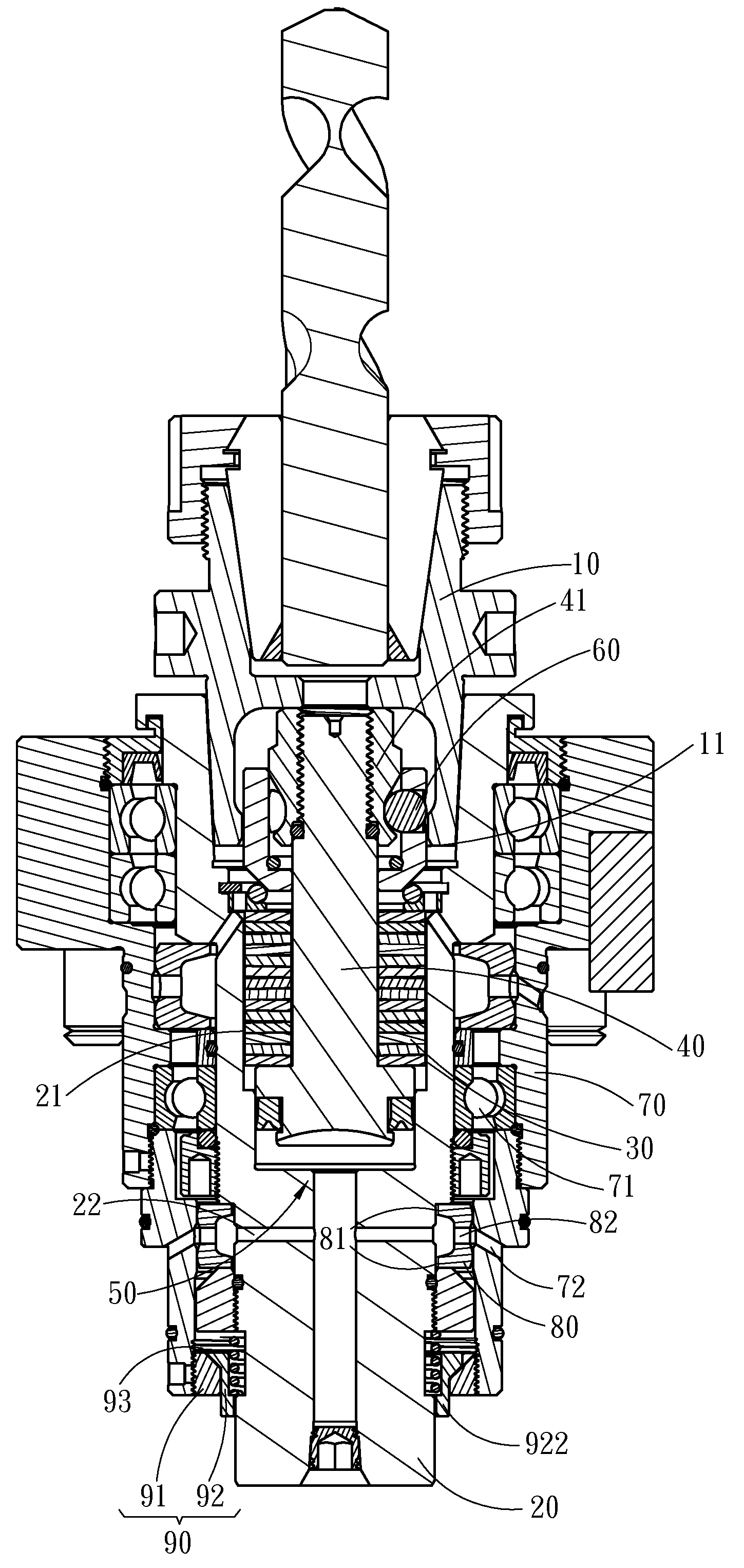
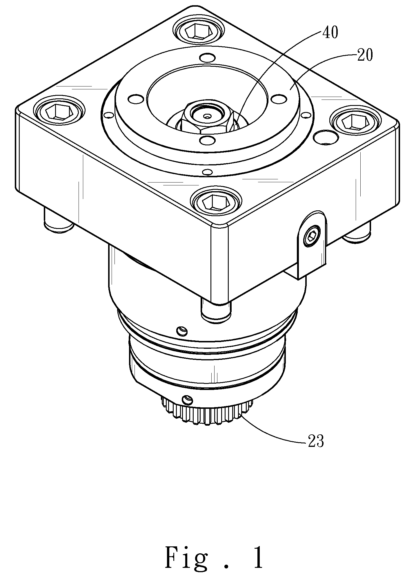
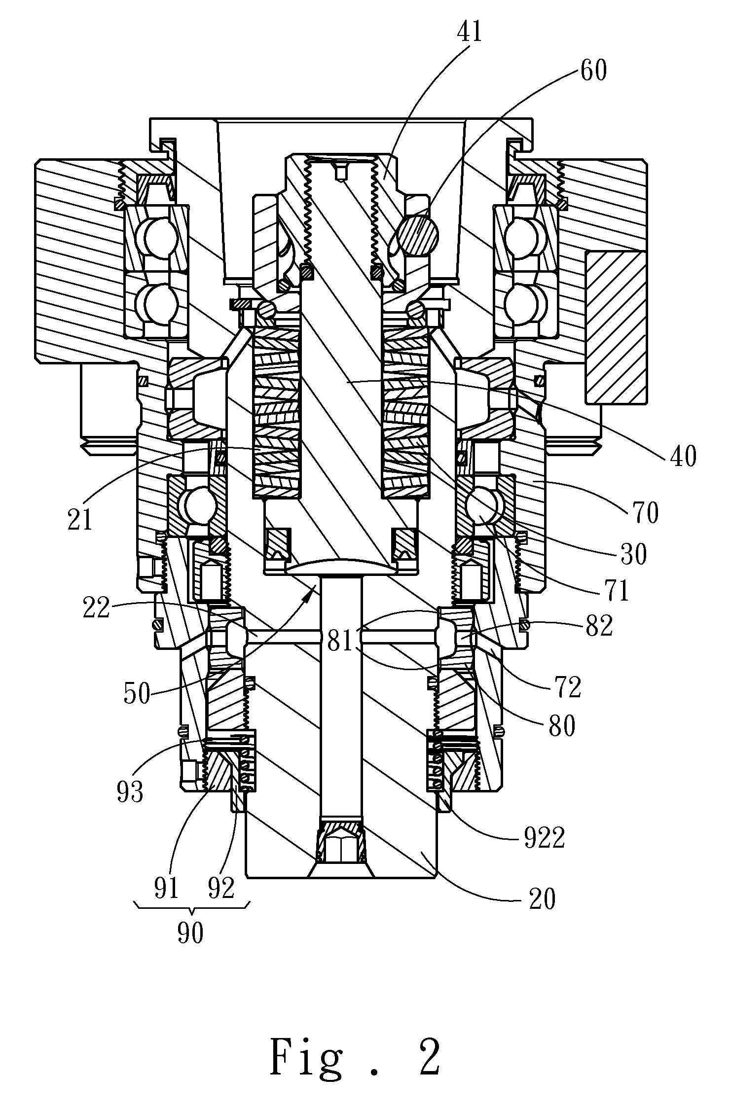
[0016]Refer to from FIG. 1 to FIG. 4B. The tool clamping device of the present invention is installed on a multifunctional machining center (not shown in the drawings) for firmly securing a tool 10 having a steel ball collar 11 and comprises a spindle 20, a disc-type spring 30, a draw rod 40, a hydraulic member 50 and a steel ball 60. The spindle 20 has an accommodation space 21 accommodating the disc-type spring 30. The disc-type spring 30 may be a compression spring. The draw rod 40 is installed inside the accommodation space 21, able to slide with respect to the spindle 20, and pressed by the disc-type spring 30 to contact the spindle 20. The draw rod 40 has a draw ring 41.

[0017]The hydraulic member 50 is arranged close to the draw rod 40 and app...


PUM

PropertyMeasurementUnit
Pressureaaaaaaaaaa

Abstract

A tool clamping device of a tool seat is installed on a multifunctional machining center for firmly securing a tool having a steel ball collar and comprises a spindle, a disc-type spring, a draw rod, a hydraulic member and a steel ball. The draw rod is able to slide with respect to the spindle, pressed by the disc-type spring to contact the spindle, and pushed by the hydraulic member to separate from the spindle. The draw rod has a draw ring, and the steel ball is accommodated in the draw ring. The disc-type spring presses the draw rod and makes the draw ring push the steel ball outward and latch the steel ball collar of the tool, whereby the tool is firmly secured. The hydraulic member applies pressure to move the draw ring to accommodate the steel ball, whereby the tool is released.

Description

FIELD OF THE INVENTION[0001]The present invention relates to a tool clamping device of a multifunctional machining center, particularly to a compact tool clamping device of a tool seat, whereby tools can be fast exchanged.BACKGROUND OF THE INVENTION[0002]The conventional manual tool clamping device of a multifunctional machining center comprises a draw rod, a rotation block, a gripper, a fixing block and a spring. The user rotates the rotation block with the draw rod, and the elastic force of the spring pushes the fixing block to slide via the irregular cross section of the rotation block to close and open the gripper, whereby the tool is clamped or released. The conventional manual tool clamping device needs a longer time to exchange tools.[0003]To automate tool exchanging, a conventional automatic tool clamping device comprises a gripper, a spring and a displacement member. The displacement member is driven to slide, and the spring restores the displacement member to a given posit...

Claims


Application Information

Patent Timeline
IPC IPC(8): B23B31/10B23Q3/12
CPCB23B31/263Y10T279/12Y10T409/309464B23B31/302
Inventor TUNG, FU-HSIANG
Owner TUNG FU HSIANG
Why Eureka
Try Eureka