Longitudinally incompressible, laterally flexible interior shaft for catheter

a catheter and longitudinal incompressible technology, applied in the field of deflectable medical catheters, can solve the problems of creating distortions and/or artifacts, not being compatible, etc., and achieve the effect of reducing the number of catheters

Inactive Publication Date: 2010-11-11
ST JUDE MEDICAL ATRIAL FIBRILLATION DIV
View PDF19 Cites 44 Cited by
  • Summary
  • Abstract
  • Description
  • Claims
  • Application Information

AI Technical Summary

Benefits of technology

[0009]This disclosure provides a family of substantially non-conductive longitudinally incompressible catheter shafts capable of repeated deflection via application of tension to cables, cords, wires, and the like. Further provided are unique catheter shafts that are essentially indifferent to electromagnetic fields, including high Tesla fields used in MRI as well as

Problems solved by technology

However, the use of the metal braiding at the distal end of a catheter may create distortions and/or artifacts in images obtained by a magnetic resonance

Method used


Image

  • Longitudinally incompressible, laterally flexible interior shaft for catheter
  • Longitudinally incompressible, laterally flexible interior shaft for catheter
  • Longitudinally incompressible, laterally flexible interior shaft for catheter

Examples


Embodiment Construction

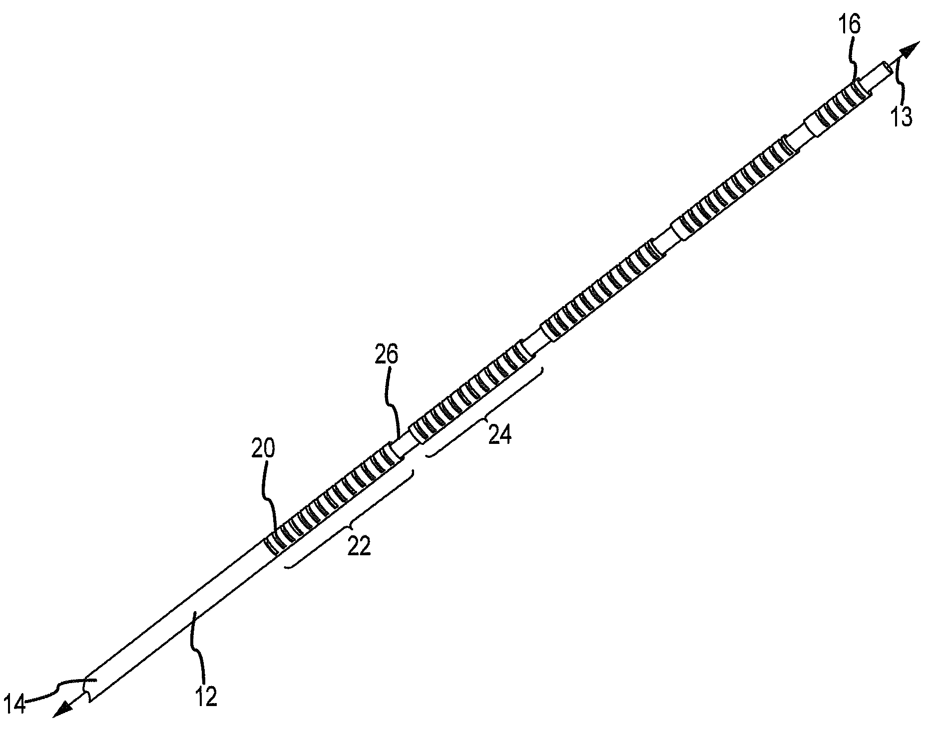
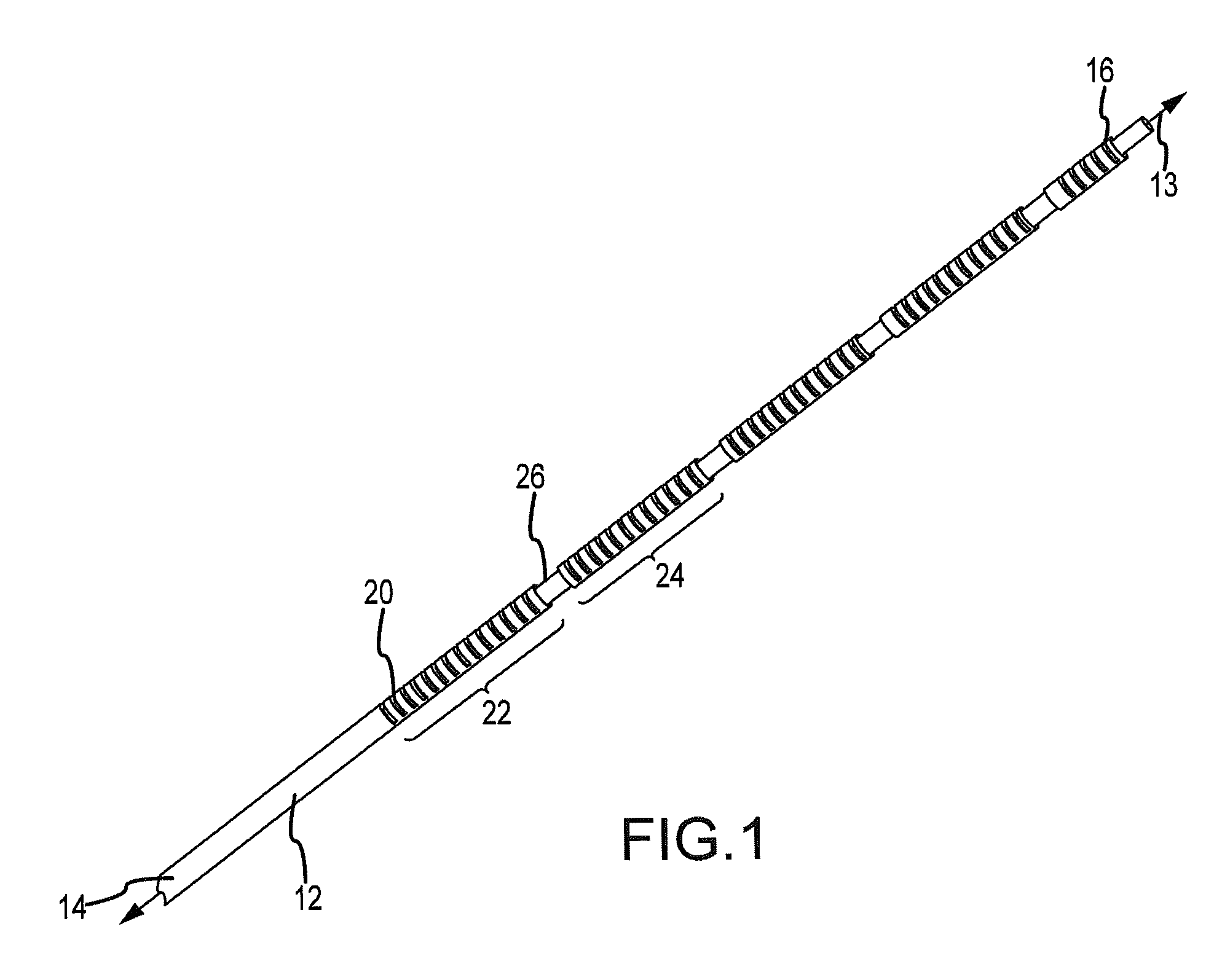
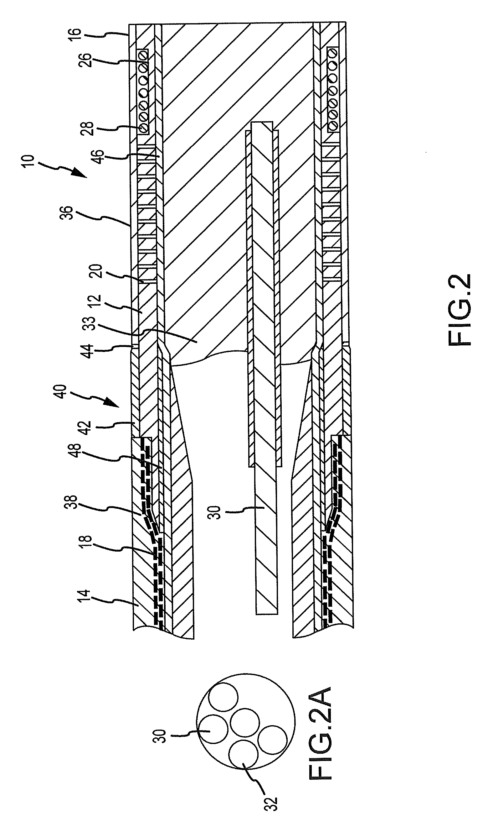
[0024]FIG. 1 illustrates a perspective view of a substantially longitudinally incompressible elongate member or shaft 12 in accordance with an embodiment of the invention. Shaft 12 is adapted to be incorporated into a medical catheter device 10 as illustrated in FIG. 2 in accordance with an embodiment of the invention. Shaft 12 is constructed of a substantially non-electrically conductive material (e.g., it can be formed of a non-metallic and / or can comprise a resin-based polymer). In an embodiment, shaft 12 may comprise polyetheretherketones (PEEK) or polyimides. In another embodiment, shaft 12 may comprise a high tensile, high modulus engineering plastic. In yet another embodiment, shaft 12 may comprise a rigid material, such as a rigid plastic or any other of a vast number of resin-based materials. Although these polymers are specifically mentioned, any of various non-metal (e.g., polymeric) materials may be utilized for shaft 12. Shaft 12 may be hollow or can have several longit...


PUM

PropertyMeasurementUnit
Angleaaaaaaaaaa
Thicknessaaaaaaaaaa
Sizeaaaaaaaaaa

Abstract

A catheter having a substantially longitudinally non-compressible non-metallic internal shaft or reinforcing member (12) is provided having proximal end, intermediate, and distal end portions. At least one of the portions of the shaft includes mechanical features that promote lateral bending of the shaft, and thus, the catheter. In one form, a plurality of spaced-apart cutouts (20,34) are formed within the shaft (12). A first of the plurality of cutouts (20) is disposed in a first plane. A second of the plurality of cutouts (34) is disposed in a second plane. The first plane and second plane can be substantially parallel. The cut-outs (20,34) can have diverse shape, size and cross-section and can be similar, identical and/or of varying dimension. In lieu of or in addition to one or more cut-outs, material removed from portions of the shaft provide relatively more or less flexibility in one or more lateral directions.

Description

CROSS-REFERENCE TO RELATED APPLICATIONS[0001]This application claims the benefit of and priority to provisional U.S. patent application No. 61 / 016,174 filed on 21 Dec. 2007 (the '174 application). The '174 application is hereby incorporated by reference as though fully set forth herein.BACKGROUND OF THE INVENTION[0002]a. Field of the Invention[0003]This disclosure relates to deflectable medical catheters. More particularly the disclosure relates to a family of substantially non-conductive and longitudinally incompressible elongate members, or shafts, incorporated into a deflectable medical catheter that repeatedly deflects without deformation and / or is compatible with high intensity electromagnetic fields.[0004]b. Background Art[0005]It is well known that devices may be inserted into a body for a variety of diagnostic and therapeutic applications. One example of an application may be to create images of the device's surroundings. Images may be acquired through visible light, ultraso...

Claims


Application Information

Patent Timeline
IPC IPC(8): A61M25/00
CPCA61B1/0055A61B18/1492A61M25/0045A61M25/0138A61M25/0053A61M25/0054A61M25/0127A61M25/0051
Inventor PETERSEN, SCOTT R.JUST, DALE E.
Owner ST JUDE MEDICAL ATRIAL FIBRILLATION DIV
Why Eureka
Try Eureka