
Artificial Discs

a technology of artificial discs and discs, applied in the field of artificial discs, can solve the problems of increased stress on the surrounding vertebrae and intervertebral discs, no longer allowing movement of damaged discs, and patient chronic pain, and achieve the effect of natural range of motion

Active Publication Date: 2013-05-02
GLOBUS MEDICAL INC
View PDF7 Cites 88 Cited by
  • Summary
  • Abstract
  • Description
  • Claims
  • Application Information

AI Technical Summary

Benefits of technology

The patent text discusses a new design for an artificial disc that can move in three to six degrees of freedom. This design provides more natural movement and other benefits, which are important for the proper function of the joint. The technical effect of this patent is the creation of a more advanced and efficient artificial disc that can better mimic the natural movement of the spine.

Problems solved by technology

In any case, a damaged disc no longer permits movement as it once did.
As the vertebrae move out of their normal, healthy position, the patient may develop chronic, and in some case debilitating, pain as nerves are compressed.
Nevertheless, the lack of motion between the fused vertebrae places increased stress on the surrounding vertebrae and intervertebral discs.
This increased stress may lead to premature failure or injury to these components, requiring further treatment.
In addition, a fusion procedure may be a major operation, requiring open back surgery and a long recovery period.
Alternatives to the open spine fusion procedure, including minimally invasive procedures and artificial disc replacements, are in various stages of development and practice, but these alternatives have yet to see widespread adoption.
Current artificial discs, however, suffer from one or more drawbacks.
Some discs do not enable a full range of motion along all degrees of freedom provided by a natural intervertebral disc.
Current discs may not properly restrict motion along a degree of freedom, which may result in hyperextension and injury to the patient.
A disc may not be compatible with minimally invasive procedures for replacing the injure disc, or a disc may only be compatible with an anterior procedure.

Method used


Image

  • Artificial Discs
  • Artificial Discs
  • Artificial Discs

Examples


Embodiment Construction

[0043]The embodiments of the disclosure and the various features and advantageous details thereof are explained more fully with reference to the non-limiting embodiments and examples that are described and / or illustrated in the accompanying drawings and detailed in the following description. It should be noted that the features illustrated in the drawings are not necessarily drawn to scale, and features of one embodiment may be employed with other embodiments as the skilled artisan would recognize, even if not explicitly stated herein. Descriptions of well-known components and processing techniques may be omitted so as to not unnecessarily obscure the embodiments of the disclosure. The examples used herein are intended merely to facilitate an understanding of ways in which the disclosure may be practiced and to further enable those of skill in the art to practice the embodiments of the disclosure. Accordingly, the examples and embodiments herein should not be construed as limiting t...


PUM

PropertyMeasurementUnit
flexibleaaaaaaaaaa
thicknessaaaaaaaaaa
distanceaaaaaaaaaa

Abstract

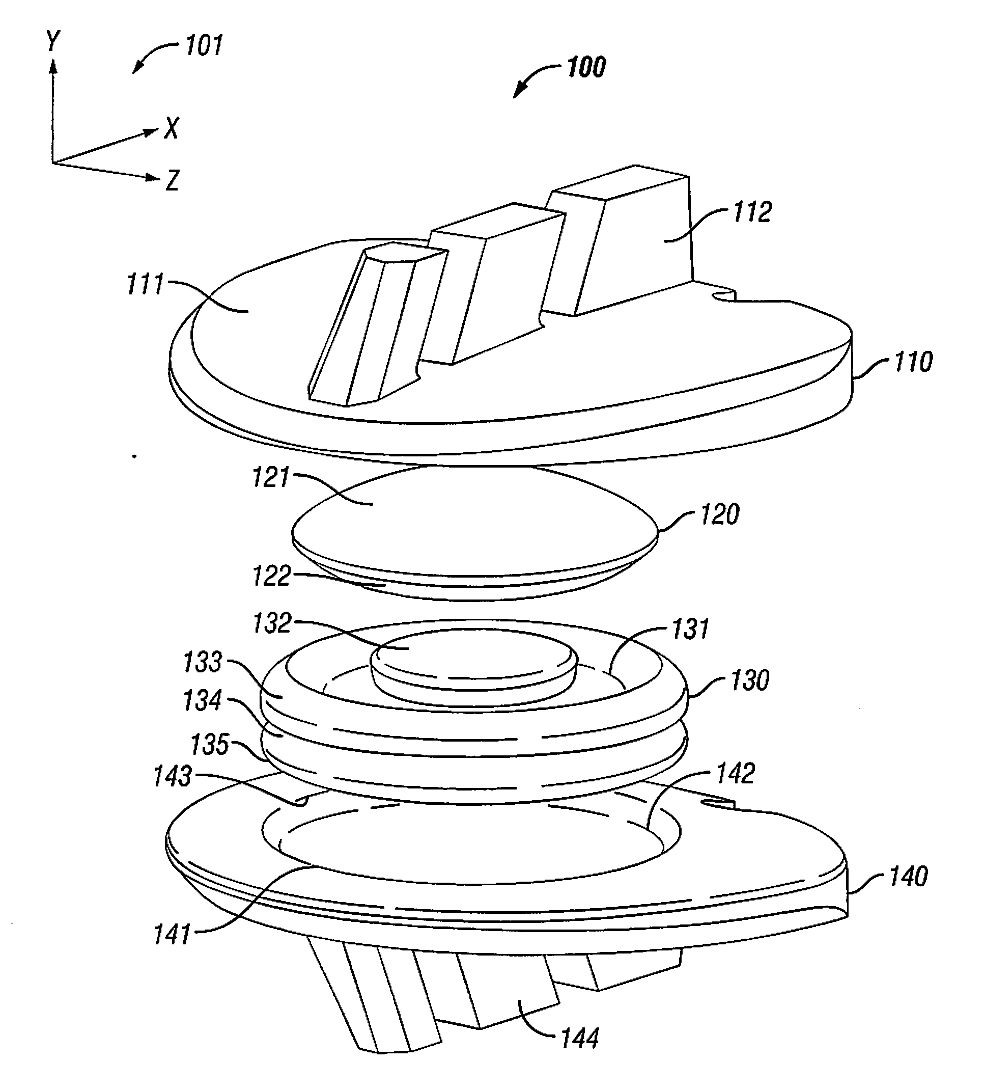
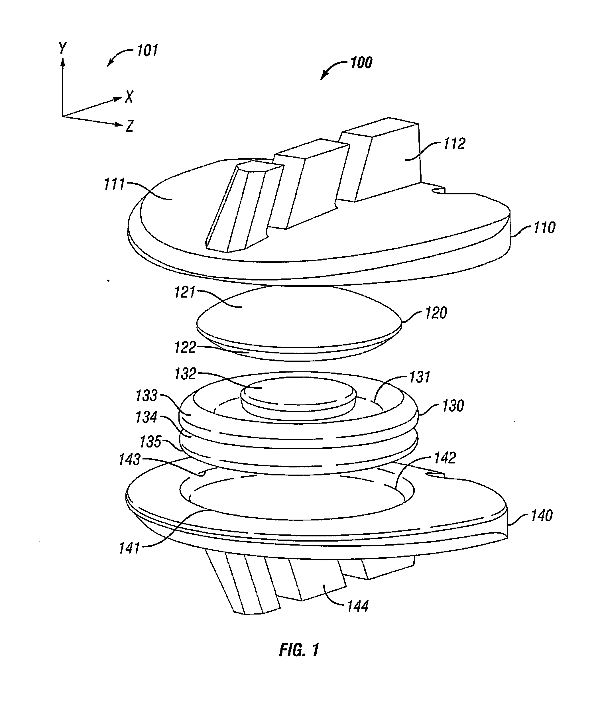
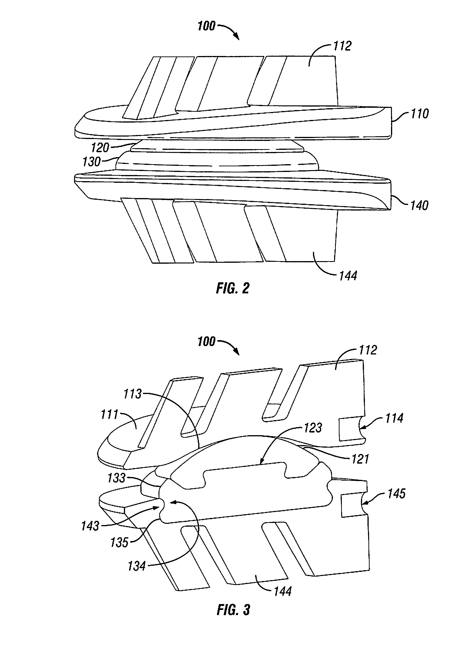
A four-component artificial intervertebral disc may provide six degrees of movement: flexion, extension, lateral bending, axial rotation, axial deflection, and anterior / posterior translation. The disc may include a superior endplate, a superior core, an inferior core, and an inferior endplate. The superior endplate may include a concave mating surface, and the inferior endplate may include a spherical mating surface. The superior endplate may roll across the superior core to provide flexion, extension, and lateral bending. The superior endplate may twist or rotate atop the superior core to provide axial rotation, and the superior endplate may slide over the superior core to provide anterior / posterior translation. The superior core may be connected to the inferior core, and the inferior core may be connected to the inferior endplate. The inferior core may be made from a flexible material that may enable the artificial disc to expand or compress vertically.

Description

BACKGROUND OF THE DISCLOSURE[0001]1. Field of the Disclosure[0002]The disclosure is directed to a device for replacing a diseased or damaged intervertebral disc. In particular, the device provides a wider range of motion than alternative treatment options, such as, for example, a spinal fusion. Specifically, the device may allow three or more degrees of freedom or different types of movement.[0003]2. Related Art[0004]The spine is composed of several individual bones, known as vertebrae. The vertebrae vary in size, shape, and function in different regions of the spine. The cervical vertebrae make up the bones of the neck and provide for much of the movement of the head. The thoracic vertebrae act as anchors for the ribs and are relatively immobile. The lumbar vertebrae, located at the base of the spine, are the largest vertebrae and allow movement and articulation of the trunk.[0005]In between each pair of vertebrae is an intervertebral disc, which consists of a fibrous outer portion...

Claims


Application Information

Patent Timeline
Patent Type & Authority Applications(United States)
IPC IPC(8): A61F2/44
CPCA61F2310/00179A61F2002/30647A61F2/4611A61F2002/30607A61F2310/00407A61F2002/30808A61F2310/00796A61F2002/30069A61F2002/30616A61F2002/30504A61F2002/30884A61F2002/30655A61F2002/30904A61F2002/30795A61F2002/30166A61F2002/3098A61F2002/30878A61F2002/30649A61F2002/30902A61F2002/30014A61F2002/30337A61F2310/00023A61F2/4425A61F2002/443A61F2310/00029A61F2/442A61F2002/30654A61F2002/305A61F2/3094A61F2002/30469
Inventor HANSELL, NOAHDWYER, EDWARDBENNETT, JEFF
Owner GLOBUS MEDICAL INC
Learn More