Precision Lid Retracting Eyedropper Device

a technology of eyedropper and lid, which is applied in the field of solution dispensing devices, can solve the problems of high cost of solution waste, many users have trouble with both types of solution dispensing systems, and many users have trouble with prescription type solutions, etc., and achieves the effect of convenient and economical manufacture, precise and consistent amount of eye solution

Inactive Publication Date: 2010-11-11
MARX ALVIN J
View PDF72 Cites 43 Cited by
  • Summary
  • Abstract
  • Description
  • Claims
  • Application Information

AI Technical Summary

Benefits of technology

[0009]Another object of the invention is to provide a precision eyedropper device that allows the user to release a precise and consistent amount of eye solution by pressing an easy release button.
[0010]Another object of the invention is to provide a precision eyedropper device that can remain sterile during multiple uses.
[0011]Another object of the invention is to provide a precision eyedropper device that allows the user to remove and replace a cartridge containing eye drop solution from a hollow housing.
[0012]A further object of the invention is to provide an alternate embodiment that allows the user to remove and replace a cartridge containing individual doses within individual chambers that can be removed and replaced from an eye drop dispensing device.
[0013]A further object of the invention is to provide a precision eyedropper device that is easy and economical to manufacture.

Problems solved by technology

Many users have trouble with both types of dispensing systems.
Additionally, these prescription type solutions can be quite expensive, making any waste of solution quite costly.
The precision needed for such applications can not be easily achieved with standard eyedropper devices.
In addition, solution is wasted due to the user blinking during the application.
Moreover, medication landing on the eyelid can cause skin irritation.
Finally, eyedropper devices currently on the market do not have the ability to remain sterile after the first use.
However, no attempt is made to hold the device in the proper location or to hold the eyelid open.

Method used


Image

  • Precision Lid Retracting Eyedropper Device
  • Precision Lid Retracting Eyedropper Device
  • Precision Lid Retracting Eyedropper Device

Examples


first embodiment

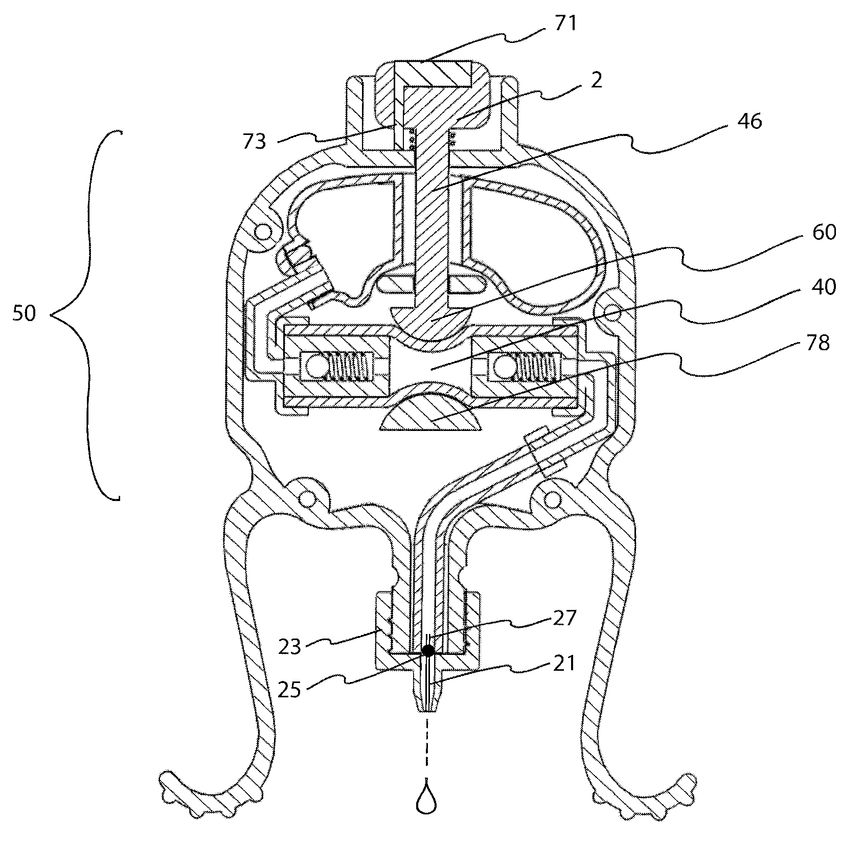
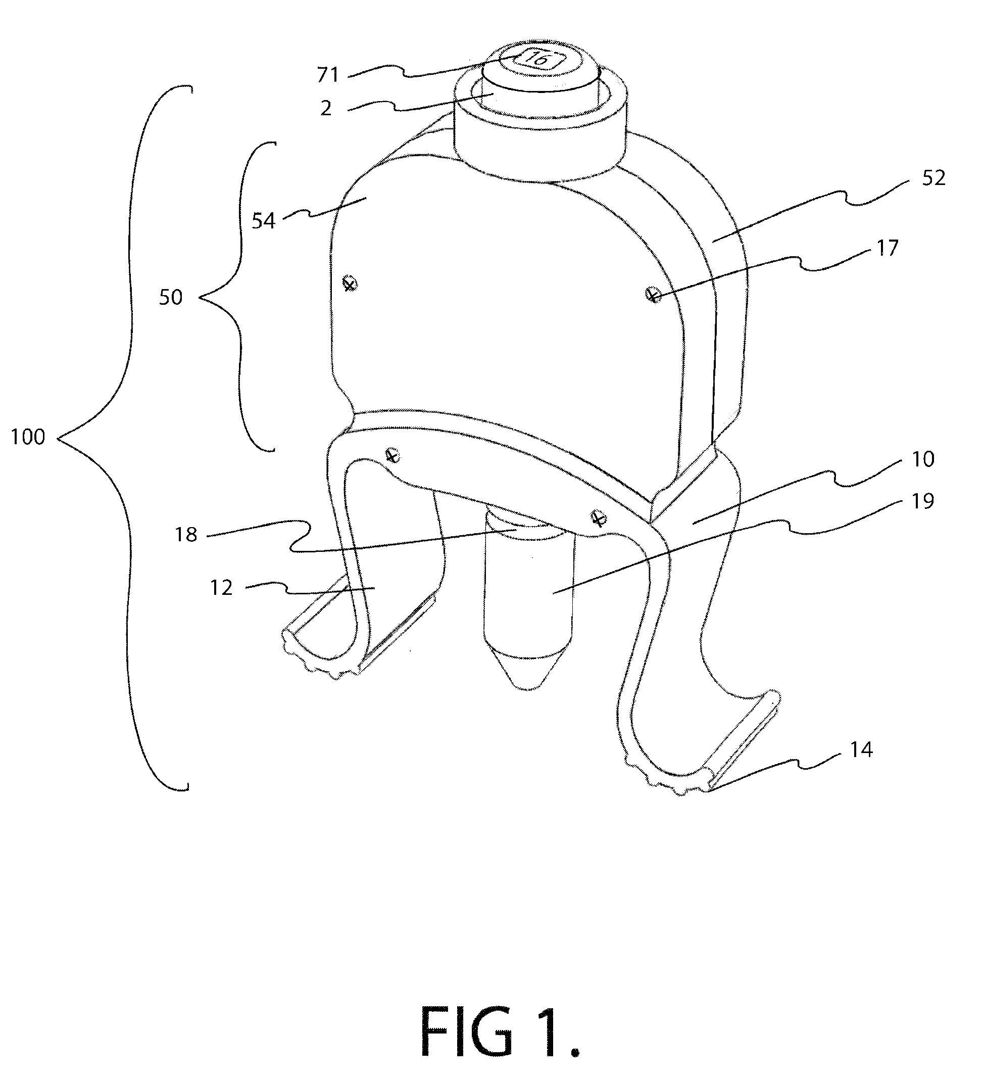
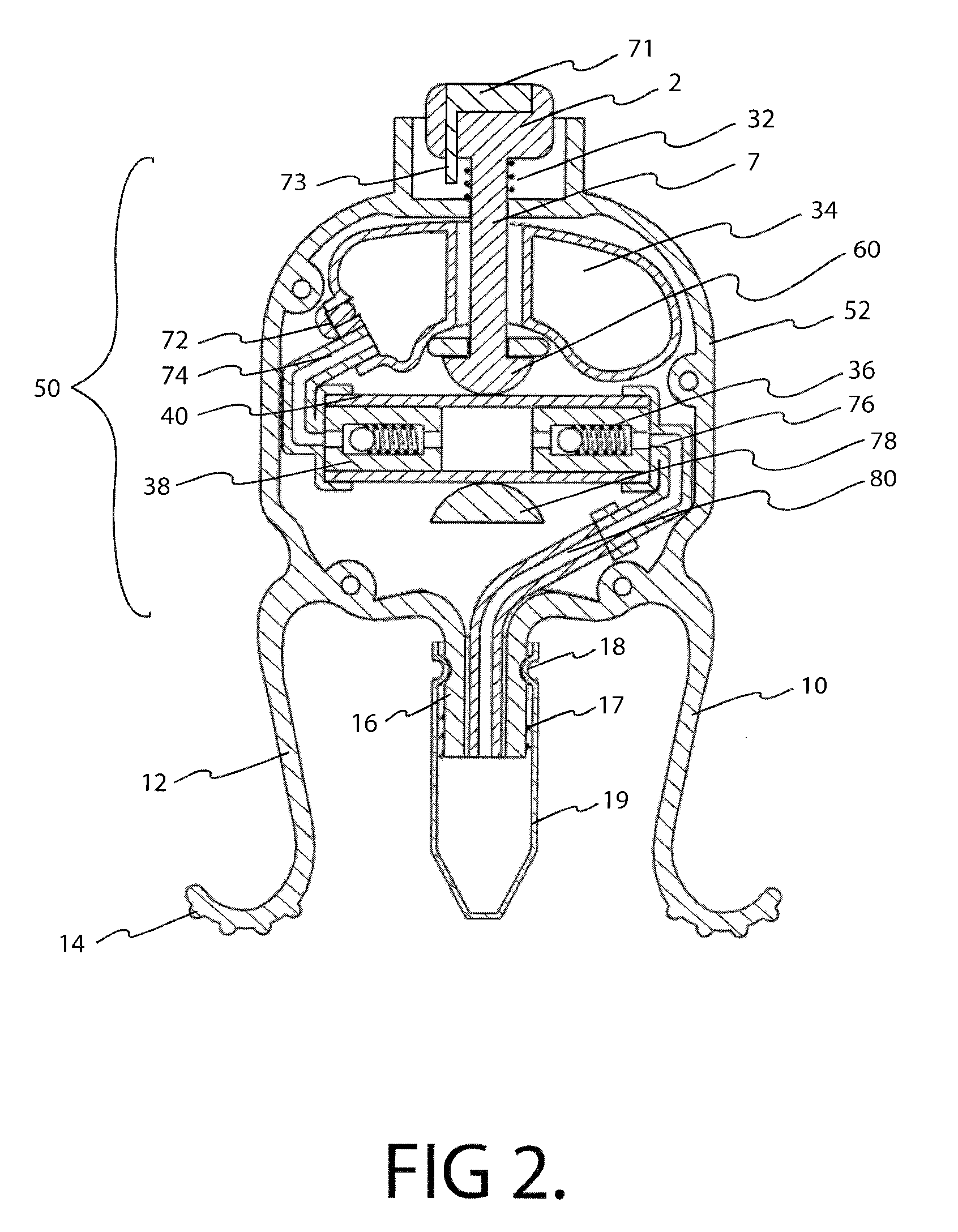
[0090]Referring now to FIG. 1 we see a front perspective view of the precision eyedropper of the present invention 100. A hollow rigid housing 50 includes an integral resilient pair of downwardly facing legs 10, 12, that terminate in J shaped feet. Traction strips 14, located on the underside of each foot are designed to help stretch the user's orbital skin during operation as will be described below. The housing assembly 50 includes a back half 52 and a front half 54 held together by screws 17 or other standard fastening means.

[0091]Push button 2, when pushed, causes a precise amount of eye drop solution to be dispensed and will be described fully below. Push button 2 includes a standard counter 71 that advances one number after each use and will be described more fully below. Exit cover 19 protects the tip portion of the device 100 during storage. For ultimate sterility performance, a plurality of exit covers 19 can be included with the device 100 and a new cover 19 can be install...

second embodiment

[0113]FIG. 21 shows a front section view of the invention 300. Ampoules 322 are wound up in a snail like pattern. They are each removably attached to each other as shown in FIG. 25. The ampoules 322 are advanced one at a time until they land under the piston member 338. The advancing mechanism works as follows. When the user lifts up on pinned 330 ever end 308, ratchet arm 334 causes pinion gear 340 to rotate which in turn causes second ratchet arm 332 to be pulled down thereby forcing the curved tip of the second ratchet arm 332 to pull an ampoule 322 down towards the push piston 320. When the lever arm 308 is fully lifted spring 342 biased activation arm 336 becomes locked in the up position when the bottom tip of the arm engages the lever 308 and holds it, and the piston 320, in the ready position. When the user presses on the release push button 310, the pinned lever arm 308 is released and forced downward by spring 316, and forcing piston 320 down onto ampoule 322 and squashing...

third embodiment

[0123]FIG. 32 is a perspective view of the invention 400. Front door 440 includes an elongated aperture 442 that allows the user to see the amount of solution 450 left in the cartridge 442 that resides inside the housing. Downwardly facing legs 410, 412 and friction strips 414 operate in a similar fashion to the previous eyedropper embodiments described above. The release of drops by pressing push button 404 will be described in detail below. Tip cover 419 protects the tip from damage and dirt during storage.

[0124]FIG. 33 is a front section view of the third embodiment 400 of the invention as defined by section line 490 in FIG. 37. Cartridge 442 can be seen in section view. The cartridge 442 is elongate and in the preferred embodiment cylindrical. The cartridge 442 is capped on top by top cover 406 that includes an air intake check valve. Cartridge 442 terminates at its bottom in tubular exit aperture 418. A removable cone shaped cap 419 protects aperture 418 and lower cylindrical p...


PUM


Abstract

Precision lid retracting eyedropper device with a hollow, rigid housing having an upper aperture that allows a push button topped piston to enter the housing where the piston can impinge on a resilient tubular member that is part of a pump assembly. The housing also includes a solution storing chamber that feeds solution to the pump assembly. A solution exit tube attached to the outgoing portion of the pump assembly emanates from the bottom part of the housing and can be directed towards the user's eye. Integral downwardly facing resilient legs are placed just above and below the user's orbital ridge so that when the legs are squeezed and released, the user's eye lids are forced open allowing the user to dispense a precise amount of solution into his or her eye. A precision eye drop solution container having the ability to retain and dispense a precise single portion of eye drop solution each time the user depresses an actuator device located on and within the housing of the container. The container includes downwardly facing legs and feet that are parallel to each other and spaced so that the foot of each leg can align and make contact with the upper and lower orbital socket of the user. The feet have rubber-like under surfaces whose soft yet gripping quality acts to help hold the eye lids of the user in the open position. The dispensing action can be automated and an LED light indicating that dispensing has occurred.

Description

CROSS REFERENCE TO RELATED APPLICATIONS[0001]This Application claims the benefit under Title 35 United States Code §120 as a Continuation-in-Part of co-pending U.S. patent application Ser. No. 12 / 319,908 filed Jan. 12, 2009, which itself further claims the benefit under Title 35 United States Code §119(e) of U.S. Provisional Application No. 61 / 026,471 filed Feb. 5, 2008; U.S. Provisional Application No. 61 / 075,768 filed Jun. 26, 2008, U.S. Provisional Application No. 61 / 086,436 filed Aug. 5, 2008, and U.S. Provisional Application No. 61 / 097,153 filed Sep. 15, 2008, the full disclosures of which are incorporated herein by reference.BACKGROUND OF THE INVENTION[0002]1. Field of the Invention[0003]This invention relates generally to the field of solution dispensing devices and more specifically to a precision lid retracting eyedropper device.[0004]2. Description of the Related Art[0005]Devices for dispensing eye drop solutions are well known. Generally, a bottle of eye drop solution inc...

Claims


Application Information

Patent Timeline
Patent Type & Authority Applications(United States)
IPC IPC(8): A61F9/00A61M35/00
CPCA61F9/0026
Inventor MARX, ALVIN J.
Owner MARX ALVIN J
Why Eureka
Try Eureka