Water conserving toilet

Inactive Publication Date: 2010-11-18
STRAIGHT FLUSH LTD
View PDF5 Cites 7 Cited by
  • Summary
  • Abstract
  • Description
  • Claims
  • Application Information

AI Technical Summary

Benefits of technology

[0024]The surface of the divider which faces the toilet bowl typically forms part of the surface of the toilet bowl, although the divider could be recessed from the toilet bowl, within the passage. Typically, the vertical distance between the base

Problems solved by technology

However, the kinetic energy required to carry solids through an S-shaped water trap limits the extent to which it is possible to conserve water in this way.
However, unless the flap is gas tight, gas will leak from the drain outlet to the surrounding atmosphere.
It is difficult to provide a reliable gas tight seal around a moveable flap, particularly as the flap may be soiled in use, a

Method used


Image

  • Water conserving toilet
  • Water conserving toilet
  • Water conserving toilet

Examples


Embodiment Construction

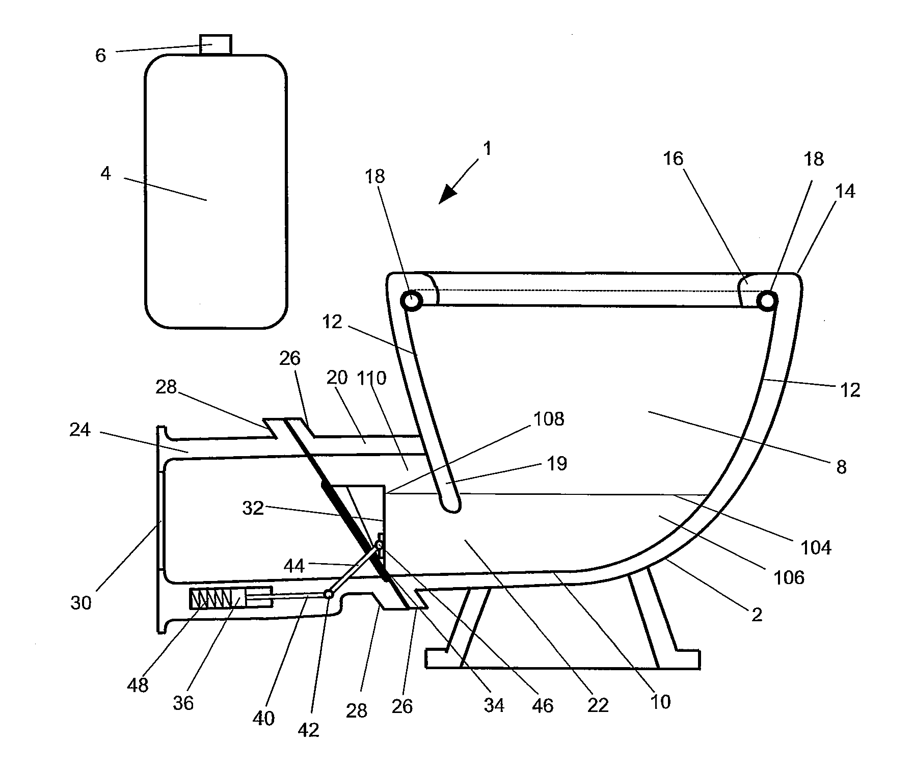
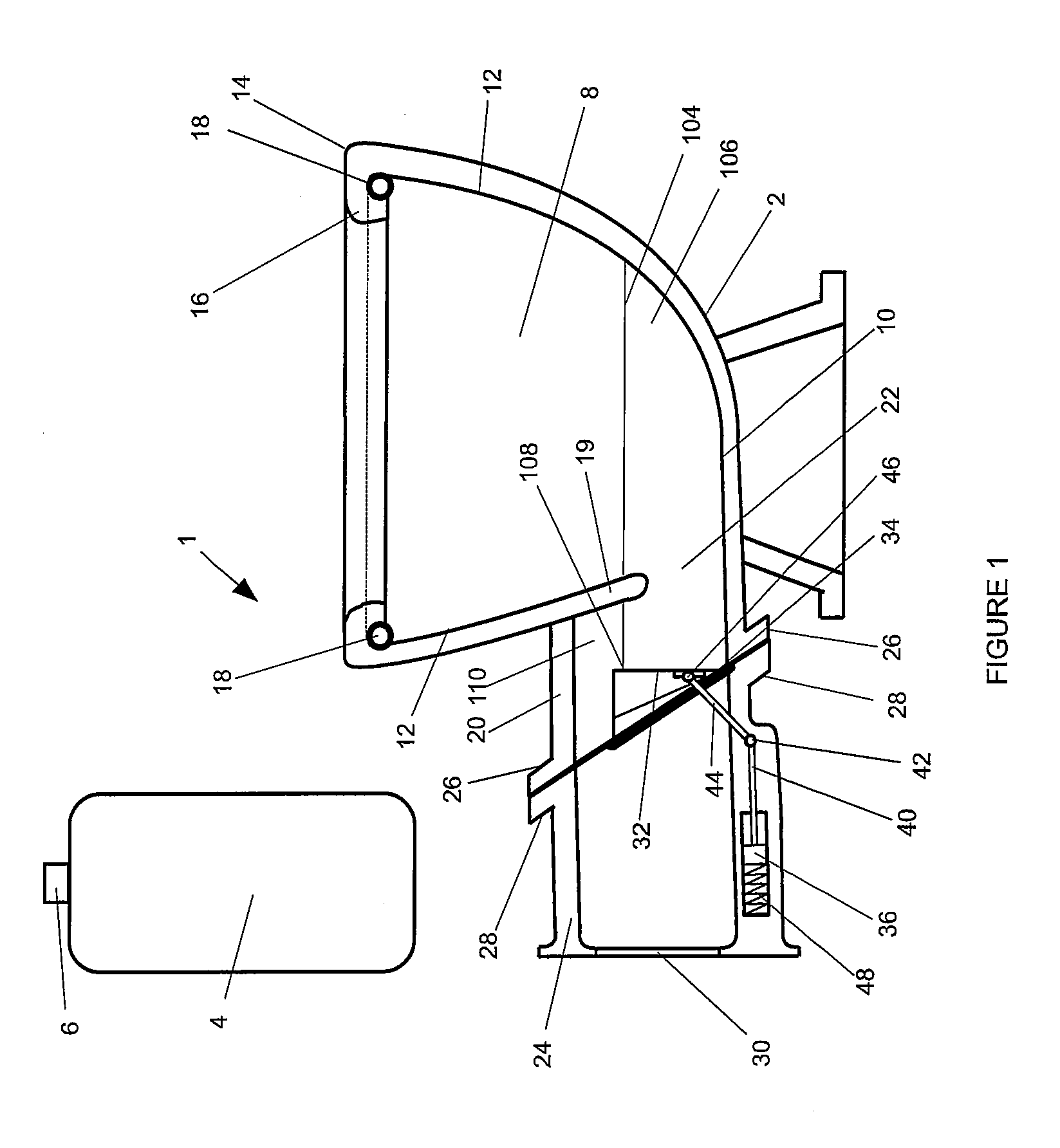
[0053]With reference to FIG. 1, a toilet 1 comprises a ceramic unit 2 and rear housing 4, which has a manually operable flush button 6 (functioning as the flush control) mounted thereon, and encloses the majority of a flush control mechanism which is described further below. The ceramic unit is shaped to define a toilet bowl 8 having an interior base 10, interior wall 12 and rim 14 with an overhanging peripheral lip 16 which lip retains a spray ring 18, the spray ring being formed from an injection moulded plastics material and comprising a plurality of apertures (not shown).

[0054]The interior wall of the ceramic unit includes a baffle 19 (functioning as the divider) which separates the toilet bowl from a first pipe section 20. An aperture 22 extends under the baffle into the first pipe section to allow the passage of water and solids from the toilet bowl into the first pipe section in use. The first pipe section is sealedly attached to a second pipe section 24 by cooperating flange...


PUM


Abstract

Disclosed is a toilet (1) comprising a toilet bowl (2), a passage which extends from the base of the toilet bowl to a drain outlet (30), and a gate (100), the gate having an open position which allows water within the toilet bowl to flow out of the drain outlet by way of the passage and a closed position in which the gate retains a continuous body of water (98) within the toilet bowl and a portion of the passage, up to a fill level (96), the toilet further comprising a divider (19) arranged to close off the passage above the fill level and to extend below the fill level at a location intermediate the toilet bowl and the water line (100) where the surface of the continuous body of water contacts the gate, to form a water trap in use when the gate is in the closed position and water is retained up to the fill level. The gate may be a flap operated by a hydraulic actuator (36), responsive to operation of a manually operable flush control, using mains water as the hydraulic fluid. Water is supplied by a spray ring around the rim of the toilet bowl. The toilet requires less water to flush than toilets including a conventional S-shaped water trap.

Description

FIELD OF THE INVENTION[0001]The present invention relates to the field of water conserving toilets.BACKGROUND TO THE INVENTION[0002]At the present time, one third or more of the water consumed by many households is used to flush conventional toilets, which have a cistern and S-shaped water trap. In conventional toilets, only a small fraction of the flush water is required to cleanse the toilet bowl and the majority of the flush water is employed to provide hydraulic energy sufficient to impart kinetic energy to the water already present in the toilet bowl and to carry solids through the S-shaped water trap.[0003]Many innovations have been proposed to control the amount of flush water dispensed by a cistern. However, the kinetic energy required to carry solids through an S-shaped water trap limits the extent to which it is possible to conserve water in this way. It is known to provide a toilet, such as a chemical toilet, in which the S-shaped water trap is dispensed with and an apert...

Claims


Application Information

Patent Timeline
IPC IPC(8): E03D11/10
CPCE03D11/10E03D5/012
Inventor RAMPEN, WILLIAM HUGH SALVIN
Owner STRAIGHT FLUSH LTD
Why Eureka
Try Eureka