Oil pump for a refrigeration compressor

a compressor and oil pump technology, applied in the direction of positive displacement liquid engines, lighting and heating apparatus, liquid fuel engines, etc., can solve the problems of high precision, occurrence of failures, and considerable increase in the production cost of said components, and achieves simple and economical construction and mounting.

Inactive Publication Date: 2010-11-18
WHIRPOOL SA
View PDF14 Cites 2 Cited by
  • Summary
  • Abstract
  • Description
  • Claims
  • Application Information

AI Technical Summary

Benefits of technology

[0013]It is an object of the present invention to provide an oil pump for a refrigeration compressor which permits and guarantees, safely and during the whole operational life of the compressor, an adequate pumping of oil to the compressor parts with relative movement, said oil pump presenting a simple and economical construction and mounting without requiring the provision of means for ascendingly centrifugally pumping the oil in the interior of the pump body.

Problems solved by technology

However, such construction requires a higher precision in mounting the impeller blade in the interior of the pump body, also favoring the occurrence of failures.
This solution presents a constructive sophistication which raises considerably the production cost of said component.

Method used


Image

  • Oil pump for a refrigeration compressor
  • Oil pump for a refrigeration compressor
  • Oil pump for a refrigeration compressor

Examples


Embodiment Construction

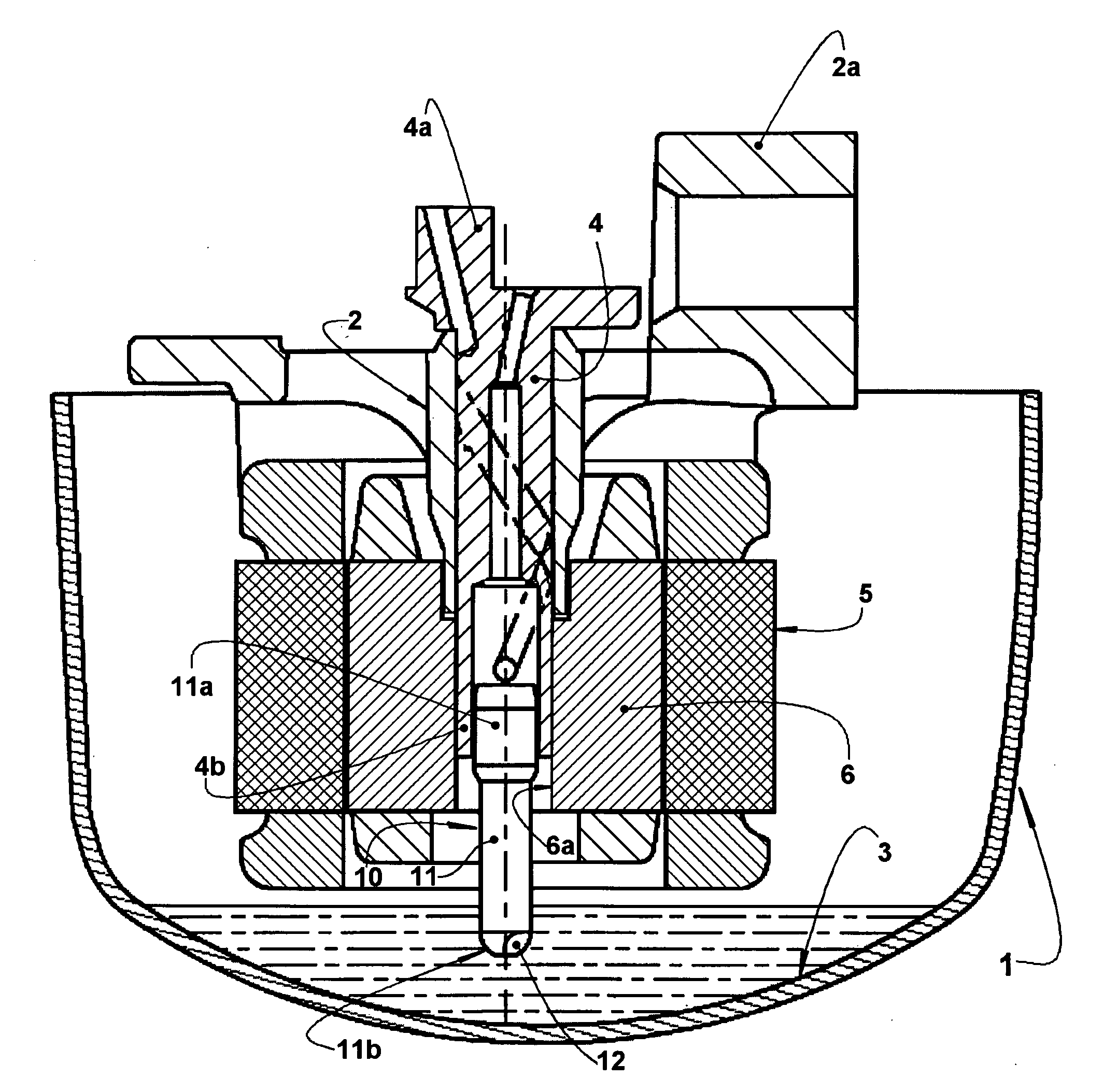
[0025]The present invention will be described for a reciprocating hermetic compressor (for example, of the type applied to a refrigeration system) presenting a generally hermetic shell 1, carrying a cylinder block 2 which defines a cylinder 2a within which actuates a reciprocating piston (not illustrated), in a lower portion of the shell 1 being defined an oil reservoir 3, wherefrom the lubricant oil is pumped, through an oil pump 10, to the movable parts of the compressor.

[0026]In the construction described herein, the refrigeration compressor is of the type which is driven by a crankshaft 4, which moves the piston, said crankshaft 4 superiorly presenting an eccentric portion 4a and being medianly journalled to the cylinder block 2 and having a lower portion 4b, which has a tubular form in the illustrated construction and which carries an oil pump 10.

[0027]The cylinder block 2 secures a stator 5 of an electric motor, further including a rotor 6 attached to the crankshaft 4, so as t...


PUM


Abstract

An oil pump is applied to a compressor which comprises a shell (1) inferiorly defining an oil reservoir (3) and carrying: a cylinder block (2) in which is journalled a crankshaft (4) carrying a pump body of the oil pump, said pump body (11) having a lower end (lib) immersed in the oil (3) and comprising: at least one collecting wall portion (12) eccentric in relation to the axis of rotation of the crankshaft (4) and which is deformed to present at least one open step (13) disposed in a plane secant to a cross section of the pump body (11) in the region of said collecting wall portion (12) and defining an opening (13a) for admitting oil to the interior of the pump body (11); and an inner impeller wall portion (14) defining a deflector transversal to the direction of admission of the oil through the open step (13) and which, with the rotation of the pump body (11), impels said oil axially and ascendingly.

Description

FIELD OF THE INVENTION[0001]The present invention refers to an oil pump for refrigeration compressors of the type which comprises a generally hermetic shell inferiorly defining an oil reservoir and internally carrying a cylinder block in which is journalled a crankshaft for driving a refrigerant gas pumping mechanism and in which is affixed an electric motor rotor, the assembly defined by the crankshaft and rotor carrying an oil pump inferiorly immersed in the oil reservoir.BACKGROUND OF THE INVENTION[0002]An important factor for the correct operation of most refrigeration compressors is the adequate lubrication of the components which have a relative movement between each other.[0003]The lubrication is obtained by pumping lubricant oil provided in an oil reservoir defined in the interior of a lower portion of a generally hermetic shell. This oil is pumped until reaching the parts of the compressor presenting relative movement, wherefrom said oil returns to the oil reservoir.[0004]I...

Claims


Application Information

Patent Timeline
Patent Type & Authority Applications(United States)
IPC IPC(8): F25B43/00
CPCF04B23/04F04B23/14F16N7/366F04B39/0253F04B39/0261F04B39/0246F04B39/02F04C29/02F16N7/36
Inventor WAGNER, NILSONMAGNHOTO, SERGIO LUIZMENDES, JOAO MANOEL
Owner WHIRPOOL SA
Why Eureka
Try Eureka