Eureka AIR delivers breakthrough ideas for toughest innovation challenges, trusted by R&D personnel around the world.

Teat rubber with shock-absorbing properties

Active Publication Date: 2010-11-18
GEA FARM TECH
View PDF7 Cites 1 Cited by
  • Summary
  • Abstract
  • Description
  • Claims
  • Application Information

AI Technical Summary

Benefits of technology

[0008]Based on this, the task of the present invention is to further develop the known teat cup liner so that at least the puncturing of the teat cup liner at the edge of the milking cup is avoided as much as possible and the mounting of the teat cup in the sleeve is improved.
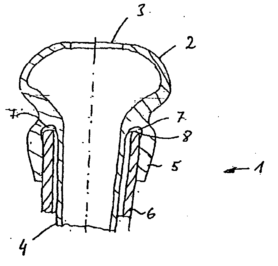
[0010]When the teat cup liner is connected to the sleeve, the holding rim surrounds an end region of the sleeve and lies against it. The recess is preferably applied in the teat cup liner in such a way that it is covered by the sleeve at least partly. The air located in the recess forms a damping pillow, so that impacts on the teat cup liner are damped. Through this design of the teat cup liner according to the invention it is not absolutely necessary to introduce a protecting ring. Surprisingly it was found that by reducing the material on the holding rim in some locations, the puncture behavior can be improved.
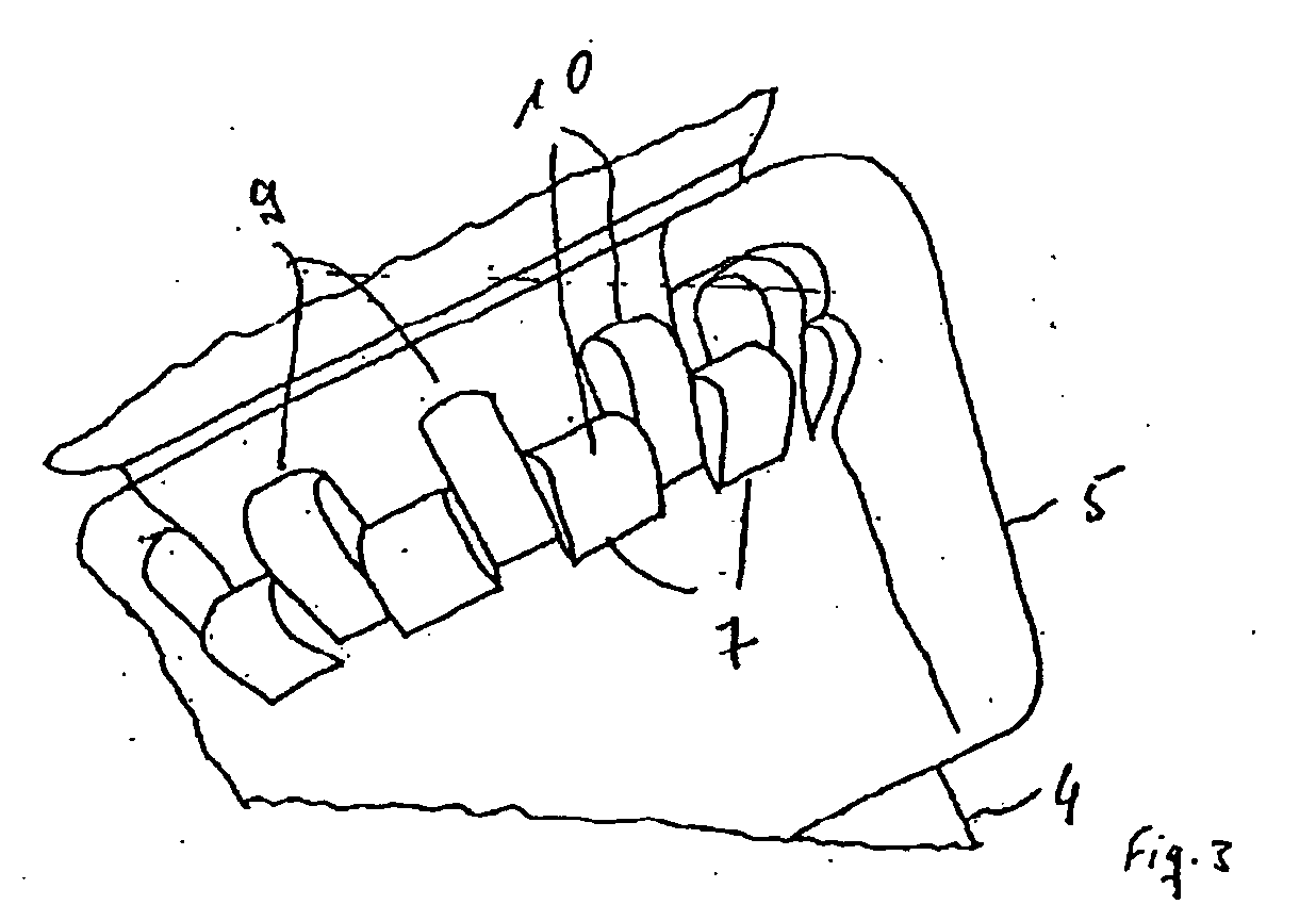
[0013]When several recesses are provided, it was found to be especially advantageous when the recesses are designed distributed not only on the edge in an essentially circumferential direction, but are also provided displaced in the axial direction with respect to one another. Through this measure, the damping property of the teat cup liner is improved even further.
[0019]The invention has numerous advantages. The teat cup liner can be made of a silicone. It is also possible to form the teat cup liner from other elastic materials. Other advantages and details of the invention are explained with the aid of the practical examples shown in the drawing, without the object of the invention being limited to these practical examples.

Problems solved by technology

However, it was found that, at the pairing of sleeve and teat cup liner, the teat cup liner may become damaged when forces, especially suddenly applied forces, are applied to the head of the teat cup liner.
This problem has already been recognized.
In such an arrangement, the mounting of the milking cup represents a problem.
However, this has the disadvantage that the head of the teat cup liner will become correspondingly large, which represents a problem, especially when milking animals whose teats are close together.

Method used


Image

  • Teat rubber with shock-absorbing properties
  • Teat rubber with shock-absorbing properties
  • Teat rubber with shock-absorbing properties

Examples


Embodiment Construction

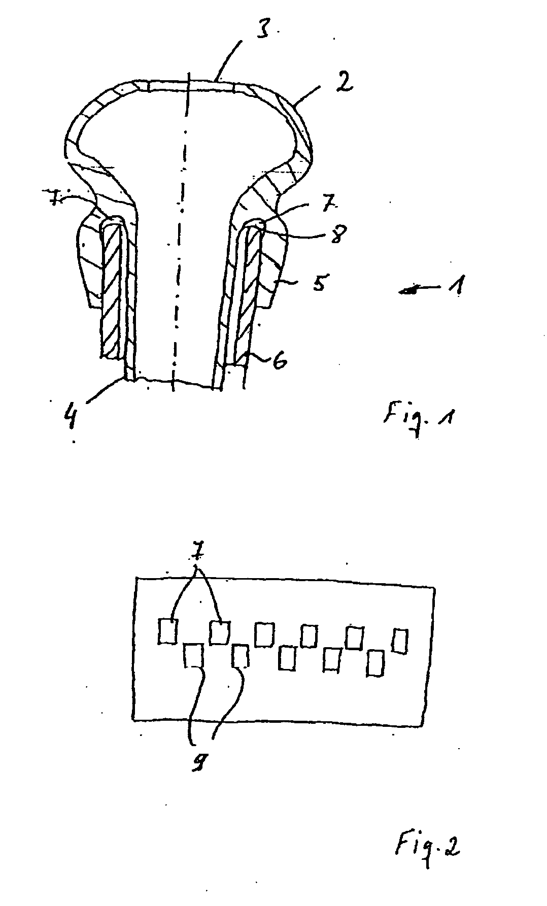
[0020]FIG. 1 shows a first practical example in cross-section,

[0021]FIG. 2 is a schematic illustration of a development of the holding rim,

[0022]FIG. 3 is a perspective view of the holding rim,

[0023]FIG. 4 shows schematically a second practical example of a teat cup liner in cross-section,

[0024]FIG. 5 shows a third practical example of a teat cup liner in cross-section,

[0025]FIG. 6 is a cross-sectional representation of a fourth practical example of a teat cup liner,

[0026]FIG. 7 is a cross-sectional representation of a fifth practical example of a teat cup liner,

[0027]FIG. 8 shows a teat cup liner with sleeve in cross-section, and

[0028]FIG. 9 shows a further practical example of a teat cup liner in cross-section.

DETAILED DESCRIPTION OF THE PREFERRED EMBODIMENTS

[0029]In FIG. 1 a teat cup liner 1 for use in a milking cup is shown schematically. The teat cup liner 1 has a head part 2. The head part 2 has an insertion opening 3 for a teat of an animal. The representation of the head par...


PUM


Abstract

A teat cup liner for use in a milking cup is disclosed. The teat cup liner has a head with an insertion opening for an animal's teat. Joined to the head is a shaft and a holding rim. The holding rim at least partially surrounds and is spaced apart from the shaft. The teat cup liner holding rim has an inner surface that defines a number of recesses to enhance the durability of the liner. The recesses can be disposed circumferentially around the inner surface of the holding rim, and they can be disposed so that they are in contact with or near an end of the teat cup sleeve.

Description

FIELD AND BACKGROUND OF THE INVENTION[0001]The invention concerns a teat cup liner for use in a milking cup with a head part that has an insertion opening for a teat of an animal and with a shaft part connecting to the head part, as well as a milking cup.[0002]A milking machine that has several milking cups is used for milking an animal, especially a cow, with a machine. As a rule, the milking cups are connected to a collecting unit through milk tubes. The milked milk is transferred to a milk tank from the collecting unit. In connection with the milking of an animal, it is also known that one can use milking cups that are connected directly to a line of the milking system, and in this case a collecting unit is not used.[0003]The milking cup comprises a sleeve in which a teat cup liner is arranged. A teat cup liner, also called molded milking tube, may have different designs. For example, according to WO 2005 / 070197, a teat cup liner is used on a milking cup with a head part on which...

Claims


Application Information

Patent Timeline
IPC IPC(8): A01J5/16
CPCA01J5/08
Inventor GRUTER, THOMASFRENSER, REINHARD
Owner GEA FARM TECH
Why Eureka
Eureka Blog
Learn More