Illumination device and control method thereof

a technology of illumination device and light-emitting diodes, which is applied in the direction of gas-filled discharge tubes, electric discharge lamps, solid cathodes, etc., can solve the problems of high cost of led modules, large volume and weight of radiators, and increased cost of led modules. , to achieve the effect of discharging hea

Inactive Publication Date: 2010-11-18
YOUNG GREEN ENERGY
View PDF4 Cites 10 Cited by
  • Summary
  • Abstract
  • Description
  • Claims
  • Application Information

AI Technical Summary

Benefits of technology

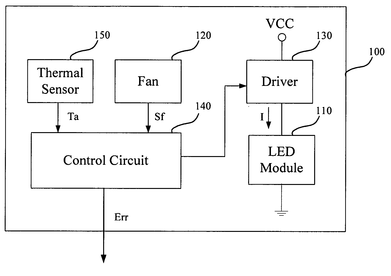
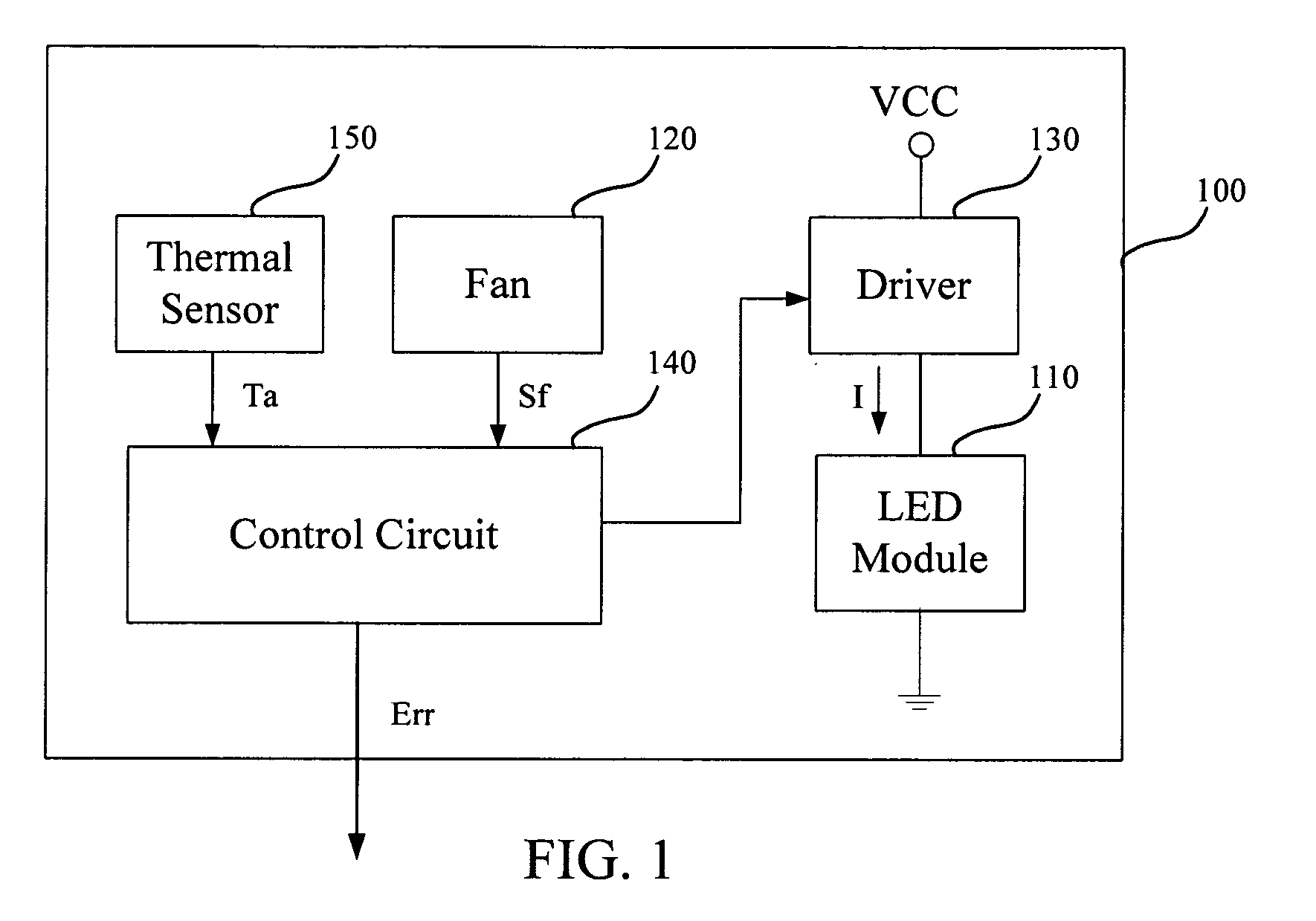
[0008]Accordingly, the invention provides a control method of an illumination device capable of dissipating heat by the light emitting diode (LED) module and protecting the LED module of the illumination device from overheating.

Problems solved by technology

The recent high intensity light emitting diode (LED) is still expensive and the LED module of an LED lighting device includes more than one LED.
For the LED illumination device, the cost of the LED module is expensive.
When the LED lighting device adopts a passive heat dissipation mechanism, i.e. natural convection or heat conducting, the volume and the weight of the radiator may become very large and heavy and thus, the heat sink becomes a heavy burden for the LED lighting device companies.
When the LED lighting device adopts an active heat dissipation mechanism, the volume of the heat sink becomes smaller, however, when the fan is broken down, the LED module may be burned.
In conclusion, how to improve the method of overheating protection for the LED module is an important issue for the LED lighting device companies.

Method used


Image

  • Illumination device and control method thereof
  • Illumination device and control method thereof
  • Illumination device and control method thereof

Examples


Embodiment Construction

[0030]In the following detailed description of the preferred embodiments, reference is made to the accompanying drawings which form a part hereof, and in which are shown by way of illustration specific embodiments in which the invention may be practiced. In this regard, directional terminology, such as “top,”“bottom,”“front,”“back,” etc., is used with reference to the orientation of the Figure(s) being described. The components of the present invention can be positioned in a number of different orientations. As such, the directional terminology is used for purposes of illustration and is in no way limiting. On the other hand, the drawings are only schematic and the sizes of components may be exaggerated for clarity. It is to be understood that other embodiments may be utilized and structural changes may be made without departing from the scope of the present invention. Also, it is to be understood that the phraseology and terminology used herein are for the purpose of description an...


PUM


Abstract

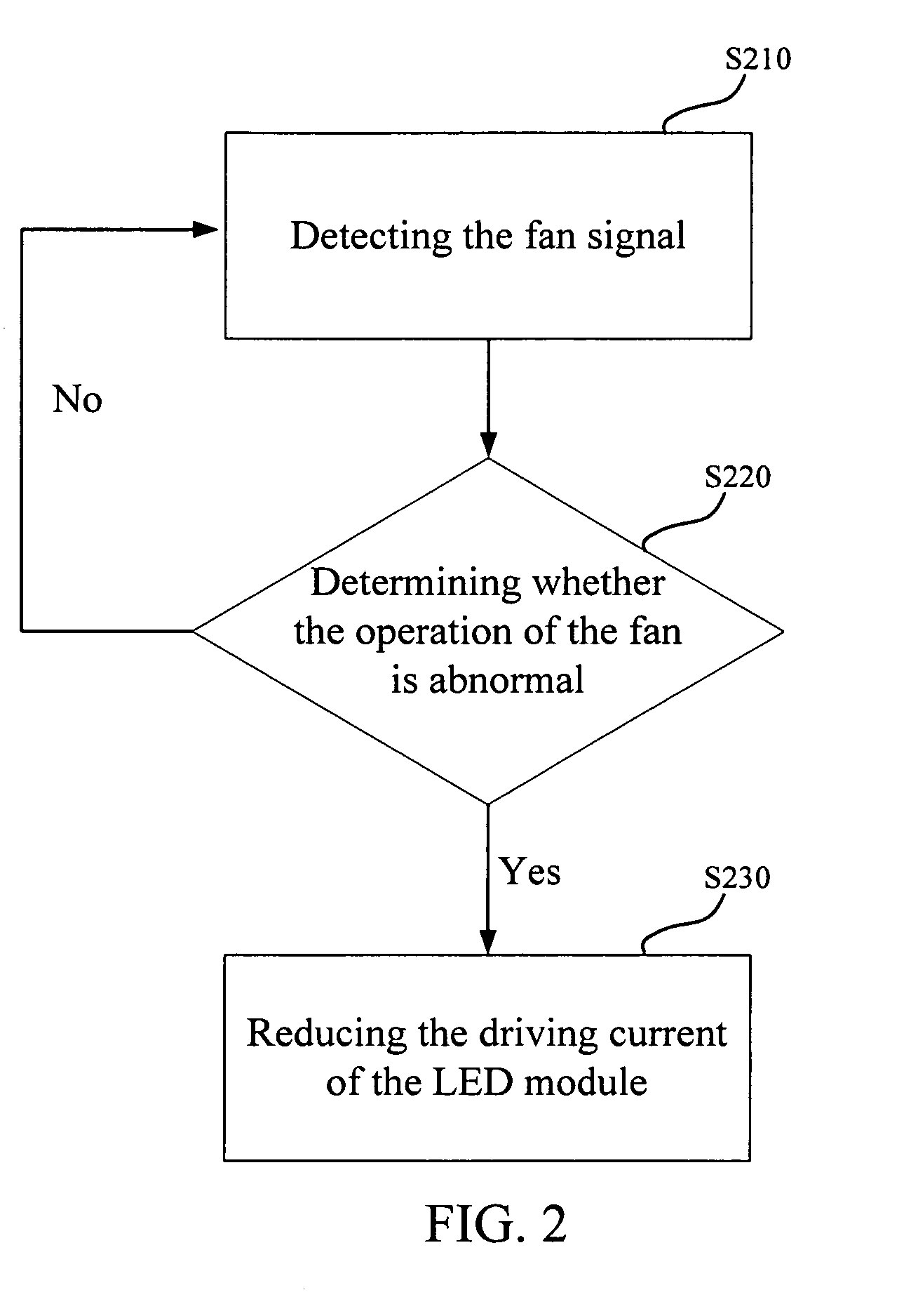
An illumination device and a control method thereof are provided. The illumination device includes a fan and a light emitting diode module capable of emitting a light beam. The control method includes: detecting a fan signal of the fan; determining whether an operation of the fan is abnormal according to the fan signal, wherein a driving current of the LED module is reduced when the operation of the fan is determined to be abnormal; and a driving current of the LED module is reduced to a predetermined rang of the normal rated driving current when the fan is determined to be stop according to the fan signal.

Description

CROSS-REFERENCE TO RELATED APPLICATION[0001]This application claims the priority benefit of Taiwan application serial no. 98116409, filed on May 18, 2008. The entirety of the above-mentioned patent application is hereby incorporated by reference herein and made a part of this specification.BACKGROUND OF THE INVENTION[0002]1. Field of the Invention[0003]The invention generally relates to an illumination device, and more particularly, to a light emitting diode illumination device with a fan and a control method thereof.[0004]2. Description of Related Art[0005]The recent high intensity light emitting diode (LED) is still expensive and the LED module of an LED lighting device includes more than one LED. For the LED illumination device, the cost of the LED module is expensive. Passive heat dissipation devices, for example, heat dissipation column or heat dissipation fin, are used for some LED modules and active heat dissipation devices, for example, a fan or a thermoelectric cooling chip...

Claims


Application Information

Patent Timeline
Patent Type & Authority Applications(United States)
IPC IPC(8): H01J61/52
CPCH05B33/0854H05B45/18
Inventor WU, SHANG-HSUANGCHANG, KEN-CHIHCHOU, CHIH-CHENGWU, CHIN-HAO
Owner YOUNG GREEN ENERGY
Why Eureka
Try Eureka