Cascade Voltage Amplifier and Method of Activating Cascaded Electron Tubes

a cascade voltage amplifier and cascade voltage technology, applied in the direction of x-ray tube targets and convertors, tubes with electrostatic control, x-ray tube targets, etc., can solve the problems of serious disadvantage, irregular operation, increase in the amount of jitter, etc., to increase the vacuum pumping and heating requirements, the effect of increasing the cos

Active Publication Date: 2010-11-18
ADVANCED FUSION SYST LLC
View PDF6 Cites 6 Cited by
  • Summary
  • Abstract
  • Description
  • Claims
  • Application Information

AI Technical Summary

Benefits of technology

[0015]The foregoing cascade voltage amplifier avoids the drawbacks of Cockcroft-Walton voltage multiplier of voltage ripple when supplying an output current with several stages. It also avoids the reliability and jitter problems of Marx generators. It further avoids the drawbacks of pulse modulators relating to inclusion of a slow and bulky pulse transformer and its susceptibility to saturation.
[0017]The foregoing method avoids the drawbacks of the prior art method of activating individual tubes mentioned above. This is accomplished by using, in a preferred form, only a single power supply to activate all the stages cascaded electron tube stages nearly simultaneously. The power supply needs to only meet the voltage requirement of the first stage tube, since the increased voltage required for each succeeding stage is provided by the voltage gain of the preceding stage. This avoids the need for larger and more costly power supplies for the succeeding stages, and for larger and substantially more complex exhaust stations involving, for instance, the use of larger feedthroughs that then require a larger vacuum enclosure and increased vacuum pumping and heating requirements.

Problems solved by technology

All of the foregoing prior art circuits have problems over which improvement would be desirable.
Among the drawbacks of the well-known Marx generator is that it suffers from reliability problems due to wear in the spark gap switches, causing irregular operation and increase in the amount of jitter.
These problems are a serious disadvantage.
Pulse modulators are limited by the requirement for a pulse transformer, which is slow, bulky and subject to saturation.
However, such prior art cascaded amplifiers have the drawbacks of being bulky and inefficient.
In the case of very high voltage tubes, the cost of suitable power supplies is very high.

Method used


Image

  • Cascade Voltage Amplifier and Method of Activating Cascaded Electron Tubes
  • Cascade Voltage Amplifier and Method of Activating Cascaded Electron Tubes
  • Cascade Voltage Amplifier and Method of Activating Cascaded Electron Tubes

Examples


Embodiment Construction

[0027]This description describes the three topics of (1) circuit topology, (2) preferred circuit implementation, and (3) method of activating cascaded electron tubes.

1. Circuit Topology

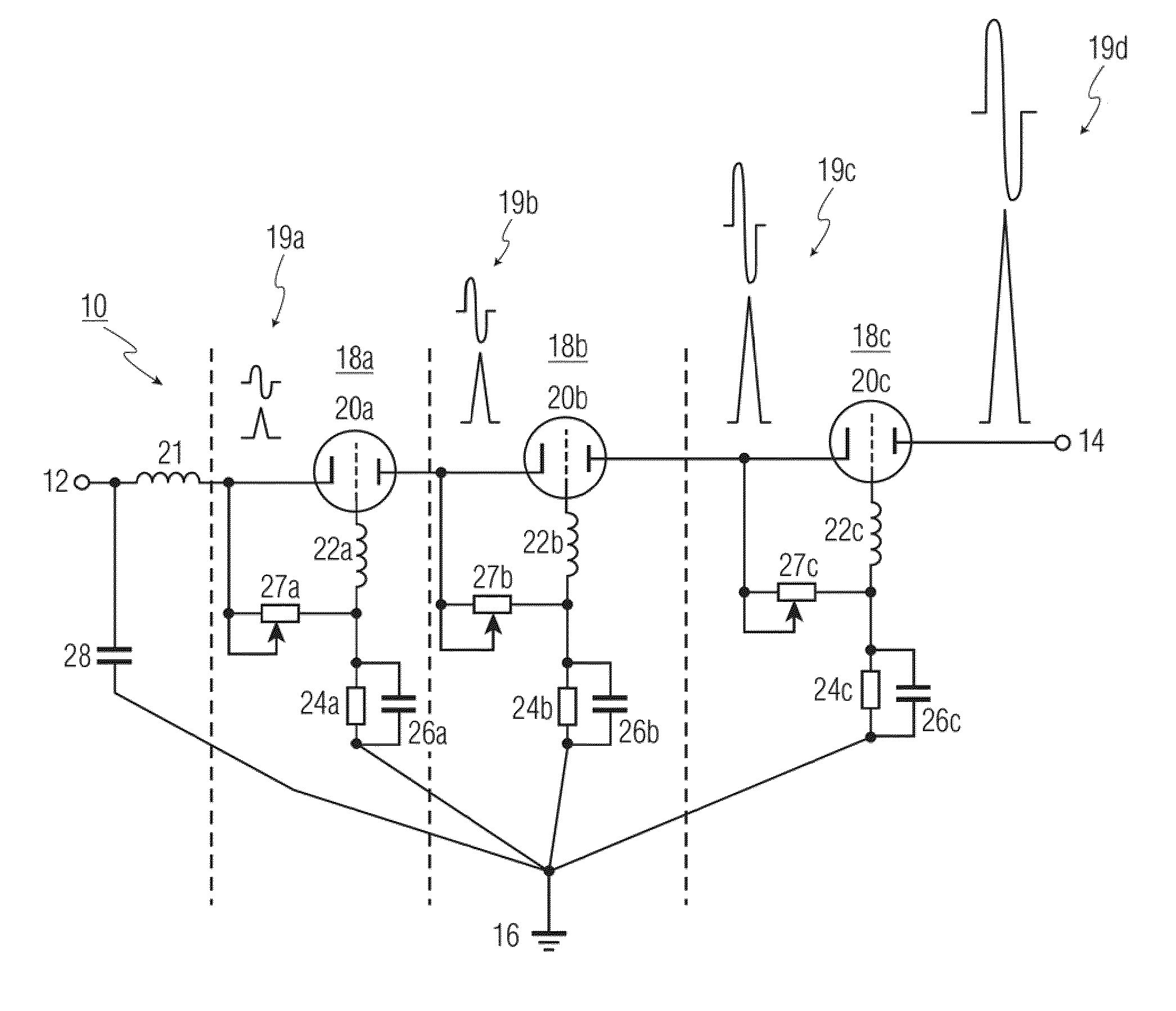
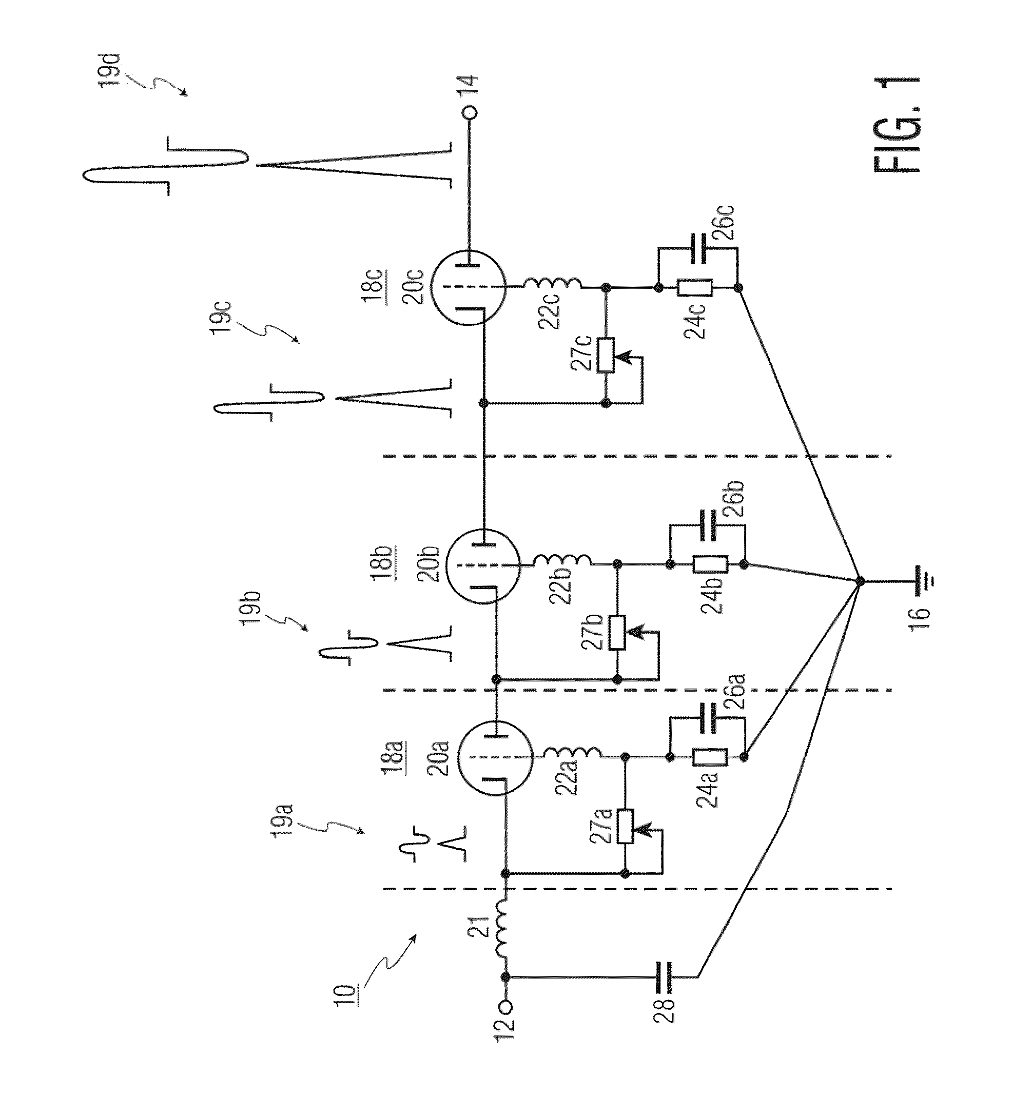
[0028]FIG. 1 shows a cascade voltage amplifier (CVA) 10 configured as a switching, and as a modified Class A amplifier, circuit. Class A amplifier operation is described below. CVA 10 includes input 12 and output 14 terminals and an earth ground 16 in accordance with good RF design practice. For the purposes of the following description, CVA 10 is designed to provide output in excess of 1000 volts.

[0029]The particular version of CVA 10 shown consists of three stages 18a, 18b and 18c. The first stage 18a includes a cold cathode field emission tube 20a of triode configuration and has a grid biased to a standoff condition by a resistor 27a, which is preferably variable. An inductor 21, known as an anti-kickback choke, blocks reverse pulses and keeps them from reaching a negative high voltage capacitor 28...


PUM


Abstract

Disclosed is a cascade voltage amplifier for producing an amplified output in pulse or continuous wave form comprises at least one non-final stage with an electron tube configured as a switching and Class A or C amplifying structure. A final stage comprises an electron tube configured as a Class A or C amplifying structure. The at least one non-final stage and the final stage are connected in series, and the amplified output has a voltage of at least 1000 volts. Further disclosed is a method of activating a plurality of cascaded electron tube stages within a common vacuum enclosure. Beneficially, a sufficient amount of energy supplied to the first stage serially propagates through any intervening stage to the final stage so as to facilitate activation of all tube stages.

Description

FIELD OF THE INVENTION[0001]The invention relates to a Class A or Class C cascade voltage amplifier for producing an amplified output in pulse or continuous form. It also relates to a method of activating a plurality of electron tube stages in cascaded structure.BACKGROUND OF THE INVENTION[0002]The production of high-energy high-voltage pulses is a fundamental requirement for many modern electronic applications. Prior art circuits for achieving pulses of this type include:[0003]1. Cockcroft-Walton voltage multiplier[0004]2. Marx Generators[0005]3. Pulse ModulatorsAll of the foregoing prior art circuits have problems over which improvement would be desirable.[0006]The Cockcroft-Walton voltage multiplier is the simplest type of voltage multiplier. First built in 1932 by Cockcroft and Walton for nuclear physics experiments. It is formed from a voltage multiplier ladder network of capacitors and diodes to generate high voltages. Unlike transformers, a Cockcroft-Walton voltage multiplier...

Claims


Application Information

Patent Timeline
Patent Type & Authority Applications(United States)
IPC IPC(8): H03F3/02
CPCH01J2235/086C02F2201/326C02F1/305C02F2303/04H01J35/065C02F2201/008H01J2235/068A61L2/0011A23L3/263A61L2/082H01J2235/062H01J2235/087B09C1/002B09C1/08H01J35/08C02F1/008C02F1/307A61L11/00H05G1/22H01J35/16H01J21/10H01J35/116H05G1/32H01J35/00H01J1/00
Inventor BIRNBACH, CURTIS A.
Owner ADVANCED FUSION SYST LLC
Why Eureka
Try Eureka