Liquid Crystal Displays Having Color Dots With Embedded Polarity Regions

a technology of color dots and liquid crystal displays, applied in the field of liquid crystal displays, can solve the problems of low contrast ratio, low viewing angle, and side of the lcd that would not receive a high quality image, and achieve the effects of enhancing fringe field effects, reducing touch mura effects, and enhancing viewing angles

Inactive Publication Date: 2010-11-18
KYORITSU OPTRONICS
View PDF3 Cites 0 Cited by
  • Summary
  • Abstract
  • Description
  • Claims
  • Application Information

AI Technical Summary

Benefits of technology

[0029]Accordingly, the present invention provides a vertically aligned liquid crystal display with reduced touch mura effects. Specifically, embodiments of the present invention use novel pixel designs that have color dots with embedded polarity regions (EPR) which amplifies fringe fields that more quickly restore the liquid crystals to their proper positions. For example, in accordance with one embodiment of the present invention, pixels are sub-divided into color components having one or more color dots (CDs). Furthermore in some embodiments of the present invention, the embedded polarity regions can be used to create or enhance fringe field effects that can induce multiple domains in the liquid crystals to enhance the viewing angle of the display.

Problems solved by technology

However, the primary drawback of conventional twisted nematic LCDs is the viewing angle is very narrow and the contrast ratio is low.
Specifically, while a viewer directly in front of an LCD receives a high quality image, other viewers to the side of the LCD would not receive a high quality image.
However, the light passing through LCD 120 is not uniform to viewers at different viewing angles.
Thus, multi-domain vertical alignment liquid crystal displays, provide wide symmetrical viewing angles, however, the cost of manufacturing MVA LCDs are very high due to the difficulty of adding protrusions to the top and bottom substrates and the difficulty of properly aligning the protrusions on the top and bottom substrates.
Specifically, a protrusion on the bottom substrate must be located at the center of two protrusions on the top substrate; any misalignment between the top and bottom substrates will reduce the product yield.
Other techniques of using physical features to the substrates, such as ITO slits, which have been used in place of or in combination with the protrusions, are also very expensive to manufacture.
Furthermore, the protrusions and ITO slits inhibit light transmission and thus reduce the brightness of the MVA LCDs.
However, the residual electric field is generally too small to tilt the liquid crystals.
However, fringe field effects are relatively small and weak, in general.
Thus, in large pixels the direction of tilting for the liquid crystals not near the edge of the pixels would exhibit random behavior and would not produce a multi-domain pixel.
Generally, fringe field effects of pixels would not be effective to control liquid crystal tilt when the pixels become larger than 40-60 μm.
However, the dot polarity pattern switching may cause other image quality issues such as flicker if all the switching elements are of the same polarity.
While the switching element point inversion driving scheme provides the most uniform power distribution, the complexity and additional costs of switching element point inversion driving scheme over switching element row inversion driving scheme or switching element column inversion driving scheme may not be cost effective.
Touch mura effects due to physical disturbance of the liquid crystals is a major issue with vertically aligned liquid crystal displays (both single domain and multiple domain).
Physical disturbance of the liquid crystals may be caused by shaking, vibration, and pressure on the display.
In particular, vertically aligned liquid crystal displays are very susceptible to touch mura effects caused by pressure on the display.
Specifically, pressure on a vertically aligned liquid crystal display may flatten the liquid crystals and cause a disturbance effect on the display.
Unfortunately, devices incorporating touch screen functionality (i.e. users of a device apply pressure on the surface of the display as a means of providing user input to the device) has become increasingly popular which may hinder acceptance of vertically aligned liquid crystal displays.

Method used


Image

  • Liquid Crystal Displays Having Color Dots With Embedded Polarity Regions
  • Liquid Crystal Displays Having Color Dots With Embedded Polarity Regions
  • Liquid Crystal Displays Having Color Dots With Embedded Polarity Regions

Examples


Embodiment Construction

[0056]As explained above, conventional vertically aligned LCDs are very susceptible to touch mura effects caused by physical disturbances to the liquid crystals. However, vertically aligned LCDs in accordance with the principles of the present invention use color dots that have embedded polarity regions (EPR) that enhance additional lateral fringe fields that help restore the liquid crystals to their proper orientation after a physical disturbance. Thus, vertically aligned LCDs in accordance with the present invention can quickly resolve touch mura effects caused by physical disturbance of the liquid crystals.

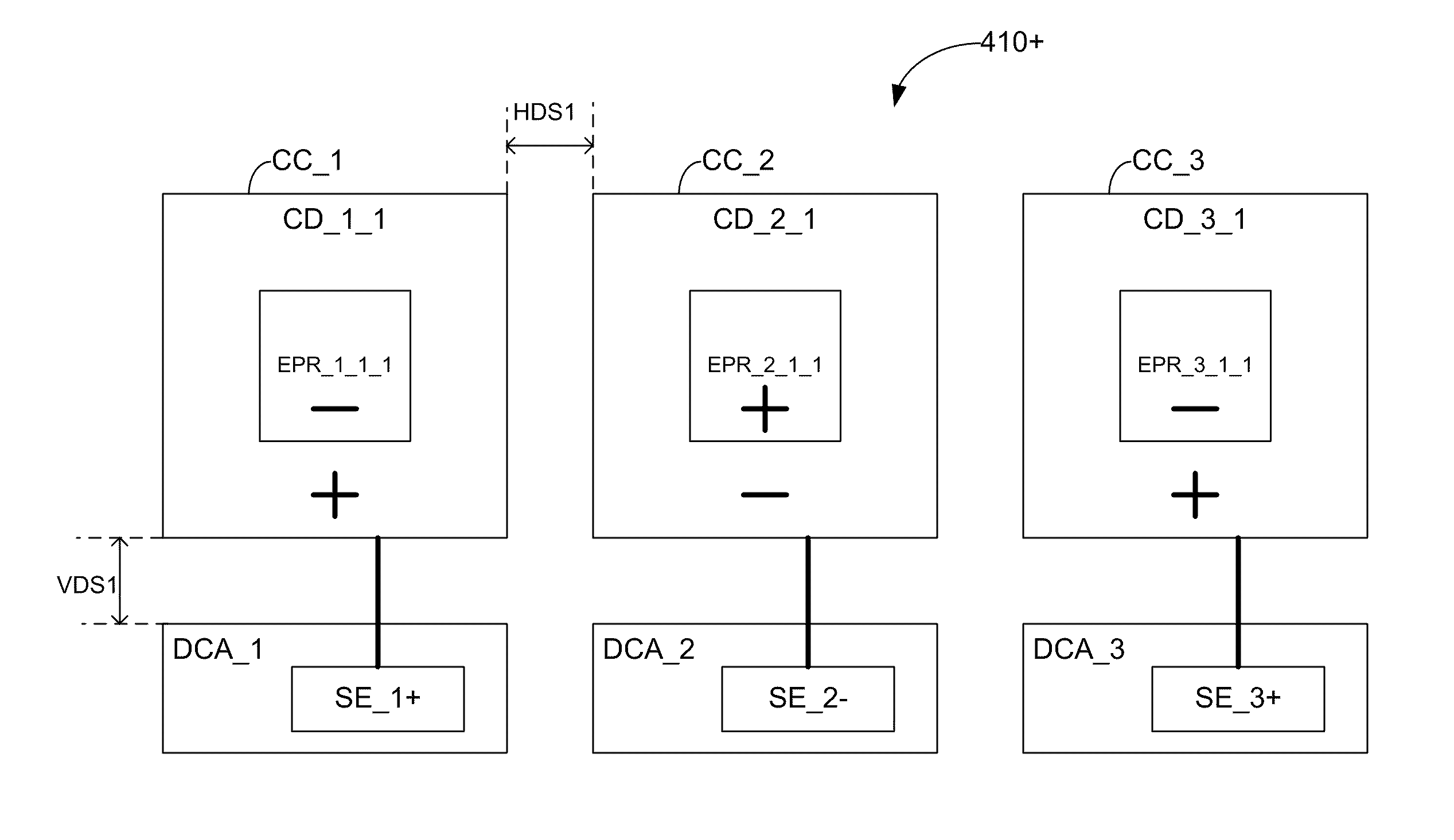
[0057]FIGS. 4(a) and 4(b) show different dot polarity patterns of a pixel design 410 (labeled 410+and 410− as described below) in accordance with one embodiment of the present invention. In actual operation a pixel will switch between a first dot polarity pattern and a second dot polarity pattern between each image frame. For clarity, the dot polarity pattern, in which the firs...


PUM


Abstract

A multi-domain liquid crystal display is disclosed. The display includes embedded polarity regions within the color dots of the display. Specifically, the embedded polarity regions have a polarity that is different from the polarity of the color dot containing the embedded polarity region. This difference in polarity enhances the fringe fields of the color dot or in some situations may create additional fringe fields. The enhanced fringe fields or additional fringe fiends can more quickly restore liquid crystals to their proper position.

Description

RELATED APPLICATIONS[0001]The present application is a Continuation-In-Part of and claims the benefit of U.S. Utility patent application Ser. No. 12 / 573,085 entitled “Pixels having Fringe Field Amplifying Regions for Multi-Domain Vertical Alignment Liquid Crystal Displays” by Hiap L. Ong, filed Oct. 2, 2009, which is incorporated herein in its entirety by reference. U.S. Utility patent application Ser. No. 12 / 573,085, is also a Continuation-In-Part of and claimed the benefit of U.S. patent application Ser. No. 11 / 751,454 (Publication serial number US 2008 / 0002072 A1), entitled “Pixels Using Associated Dot Polarity for Multi-Domain Vertical Alignment Liquid Crystal Displays” by Hiap L. Ong, filed May 21, 2007, which is incorporated herein in its entirety by reference. U.S. Utility patent application Ser. No. 11 / 751,454 claimed the benefit of U.S. Provisional Patent Application Ser. No. 60 / 799,815, entitled “Multi-domain Vertical Alignment liquid crystal display with row inversion dr...

Claims


Application Information

Patent Timeline
Patent Type & Authority Applications(United States)
IPC IPC(8): G09G3/36
CPCG02F1/133707G02F1/1393G02F2201/123G09G3/3614G09G2320/028G09G2300/0439G09G2300/0452G09G2300/0491G09G2320/0242G09G3/3648
Inventor ONG, HIAP L.
Owner KYORITSU OPTRONICS
Why Eureka
Try Eureka