Methods and Apparatus for Optical Amplitude Modulated Wavefront Shaping

a technology of optical amplitude modulation and wavefront shaping, applied in the direction of distance measurement, instruments, and reradiation, can solve problems such as the source of error of very long baseline interferometry

Active Publication Date: 2010-11-18
PARKER DAVID H
View PDF7 Cites 25 Cited by
  • Summary
  • Abstract
  • Description
  • Claims
  • Application Information

AI Technical Summary

Benefits of technology

[0052]The specification discloses a theoretical foundation explaining the effects of d...

Problems solved by technology

This could also be a source of error for very long baseline interferometry (VLBI) as ex...

Method used


Image

  • Methods and Apparatus for Optical Amplitude Modulated Wavefront Shaping
  • Methods and Apparatus for Optical Amplitude Modulated Wavefront Shaping
  • Methods and Apparatus for Optical Amplitude Modulated Wavefront Shaping

Examples


Embodiment Construction

[0049]While modulation of light at microwave frequencies is well known in the art, rapid advances have been made in the generation of terahertz (THz) waves, which span the spectrum between microwaves and infrared radiation. For example, U.S. Pat. No. 7,684,023 to Kang et al., discloses Apparatus and method for generating THz wave by heterodyning optical and electrical waves. It will be recognized that the invention will have application for these wavelengths also.

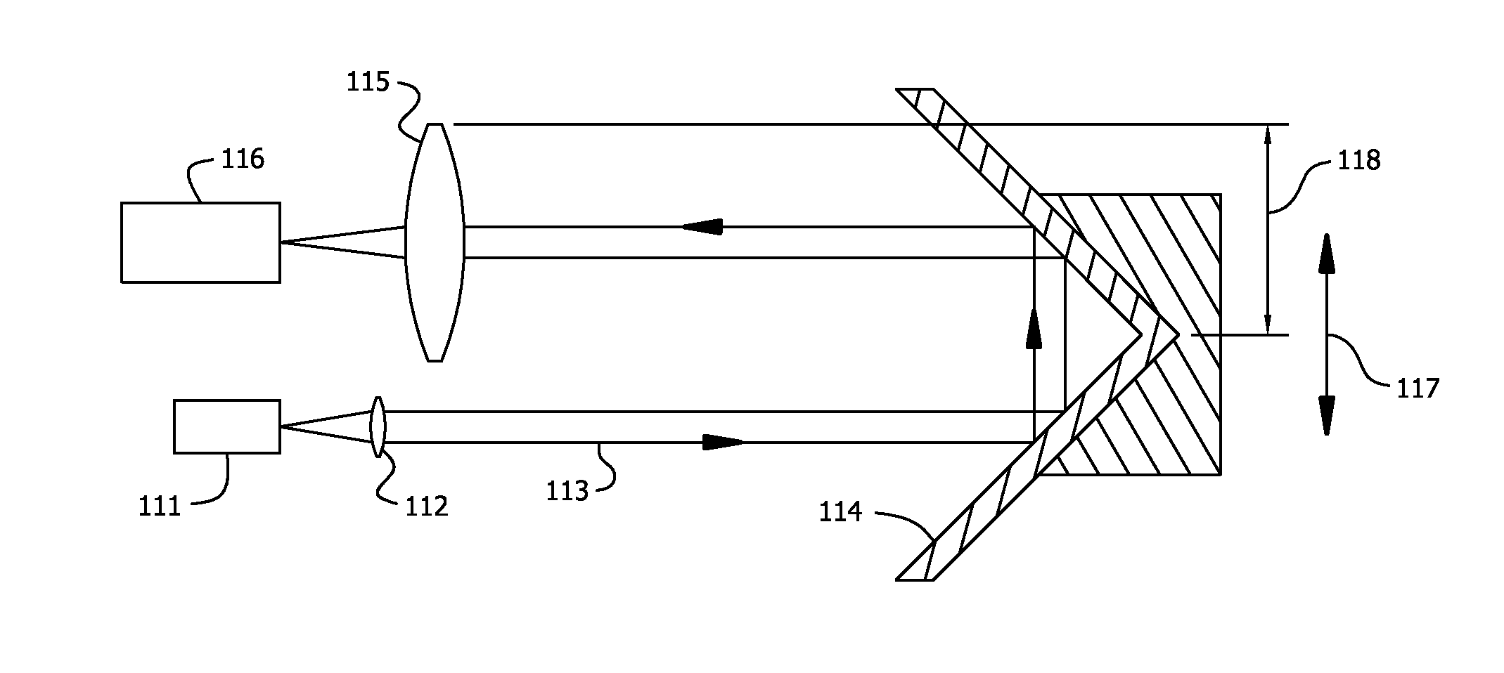
[0050]While radio telescopes employ catoptric main reflectors, many receivers employ dielectric lenses to correct for aberrations of the main reflector, subreflector, or other optical elements, and thus temporally modulated signals, such as pulsars (rotating neutron stars that emit light pulses at frequencies up to ≈1 kHz) may be subject to additional dispersion due to the optics. This could also be a source of error for very long baseline interferometry (VLBI) as explained in Interferometry and Synthesis in Radio Astronomy...


PUM


Abstract

The invention extends classical time-invariant optical design to include optical amplitude modulated light, using tools from communications theory. Effects of dispersion are derived from first principles.

Description

1 FIELD OF THE INVENTION[0001]This invention is related to the design, analysis, and construction of optical components and systems for radio frequency (RF), or higher frequency, temporally modulated optical wavefronts, and in particular, wave-fronts in optical time-of-flight or phase measurement instruments using dispersive optical elements in the optical train. Elements from communications theory, including amplitude modulation (AM) and analysis in the Fourier transform frequency domain are unified with classical optics in order to correct for wavefront distortion of a modulation envelope at the beat note frequency produced by two optical carrier sidebands, or a group of optical side-bands, in order to optimize measurement, of pulse, chirp, phase, or the like systems wherein the measurement is integrated over an area of the wavefront at a detector, and demodulated at the modulation frequency, or heterodyned to an intermediate frequency (IF).2 BACKGROUND OF THE INVENTION2.1 Amplitu...

Claims


Application Information

Patent Timeline
IPC IPC(8): G01C3/00G02F1/01G02B3/00
CPCG01S7/497G01S17/006G02B13/146G02F1/01G02B27/0025G02B27/46G02B26/06
Inventor PARKER, DAVID H.
Owner PARKER DAVID H
Why Eureka
Try Eureka