Liquid tank, viewing device for under-liquid observation, and optical film

a technology for viewing devices and liquid tanks, applied in the direction of liquid/fluent solid measurement, instruments, optical elements, etc., can solve the problems of difficult removal of films, significant deterioration of viewing, and adhesion to films, and achieve easy cleaning, excellent visibility and durability, and reduced coloring

Inactive Publication Date: 2010-11-18
SHARP KK
View PDF13 Cites 12 Cited by
  • Summary
  • Abstract
  • Description
  • Claims
  • Application Information

AI Technical Summary

Benefits of technology

[0058]The liquid tank and the first optical film of the present invention can provide a liquid tank excellent in visibility and durability and easy to clean. More specifically, the use of the liquid tank and the first optical film of the present invention allows a marked decrease in coloring and an improvement in durability of the internal surface of the liquid tank, and further allows easily cleaning the internal surface of the tank. Further, the refractive index of the protective layer can be easily made substantially equivalent to that of a liquid to be stored in the tank. As a result, the reflection on the surfaces, particularly on the internal surface of the tank can be markedly decreased. In addition, the protective layer and air are usually different in refractive index, so that the liquid level in the tank can be readily determined by being viewed from the outside through the transparent wall.
[0059]The viewing device and the second optical film of the present invention can provide a viewing device for under-liquid observation excellent invisibility and durability and easy to clean. More specifically, the use of the viewing device and the second optical film of the present invention allows a marked decrease in coloring and an improvement in durability of the external surface of the viewing device, and further allows easily cleaning the external surface of the device. Further, the refractive index of the protective layer can be easily made substantially equivalent to that of a liquid to be in contact with the device. As a result, the reflection of ambient light on the surfaces, particularly on the external surface, of the device can be markedly decreased.

Problems solved by technology

Also in a viewing window-including tank or a viewing device each including the optical film, stains are easy to adhere to the film but it is difficult to remove them therefrom.
Further, ambient light is reflected on the interface between media with different refractive indexes, i.e., water and the release sheet or the paper, and the viewing is significantly deteriorated as a result.
However, this multi-layer structure leads to poor wavelength dispersion characteristic of the anti-reflection film to cause coloring of reflected light.
When disposed on the internal surface of a transparent wall or the external surface of a transparent window, for example, the multi-layer anti-reflection film is readily damaged by hit of fishes to the wall or window.
That is, the multi-layer anti-reflection film usually has poor durability.
The multi-layer anti-reflection film is an expensive material and requires complicated production steps, and therefore it might be lack in versatility.

Method used


Image

  • Liquid tank, viewing device for under-liquid observation, and optical film
  • Liquid tank, viewing device for under-liquid observation, and optical film
  • Liquid tank, viewing device for under-liquid observation, and optical film

Examples


embodiment 1

[0079]The liquid tank of Embodiment 1 has a transparent wall, and on the internal surface of the wall, a first moth-eye layer having a moth-eye structure and a protective layer covering the moth-eye structure are disposed in this order from the wall side.

[0080]Inside the tank of the present Embodiment, a material containing at least a liquid is stored. An observer views the content of the tank, such as under-liquid objects (e.g., living creatures), the liquid level, the liquid itself from the outside through the transparent wall. Thus, the tank of the present Embodiment is suitably used as an aquarium or observation tank, including a water tank and a tank with a viewing window.

[0081]According to the tank of the present Embodiment, the first moth-eye layer having a moth-eye structure allows markedly reducing light reflection on the interface between the first moth-eye layer and the protective layer (e.g., a reflectance of 0.1% or lower). The transparent wall and the liquid (hereinaft...

embodiment 2

[0119]The viewing device for under-liquid observation of Embodiment 2 includes a transparent window, and on the external surface of the window, a first moth-eye layer having a moth-eye structure and a protective layer covering the moth-eye structure are disposed in this order from the window side.

[0120]The external surface of the transparent window means a surface on the side opposite to the observer side.

[0121]Thus, in Embodiment 2, the first moth-eye layer and the protective layer mentioned in Embodiment 1 are applied to a viewing device for under-liquid observation. Embodiment 2 is mentioned below mainly with reference to embodiments and effects different from those in Embodiment 1, and the same contents are omitted.

[0122]The viewing device of the present Embodiment is used with at least the transparent window being in contact with liquid. Through this transparent window, the observer views under-liquid objects.

[0123]The viewing device of the present Embodiment includes the first...

example 1

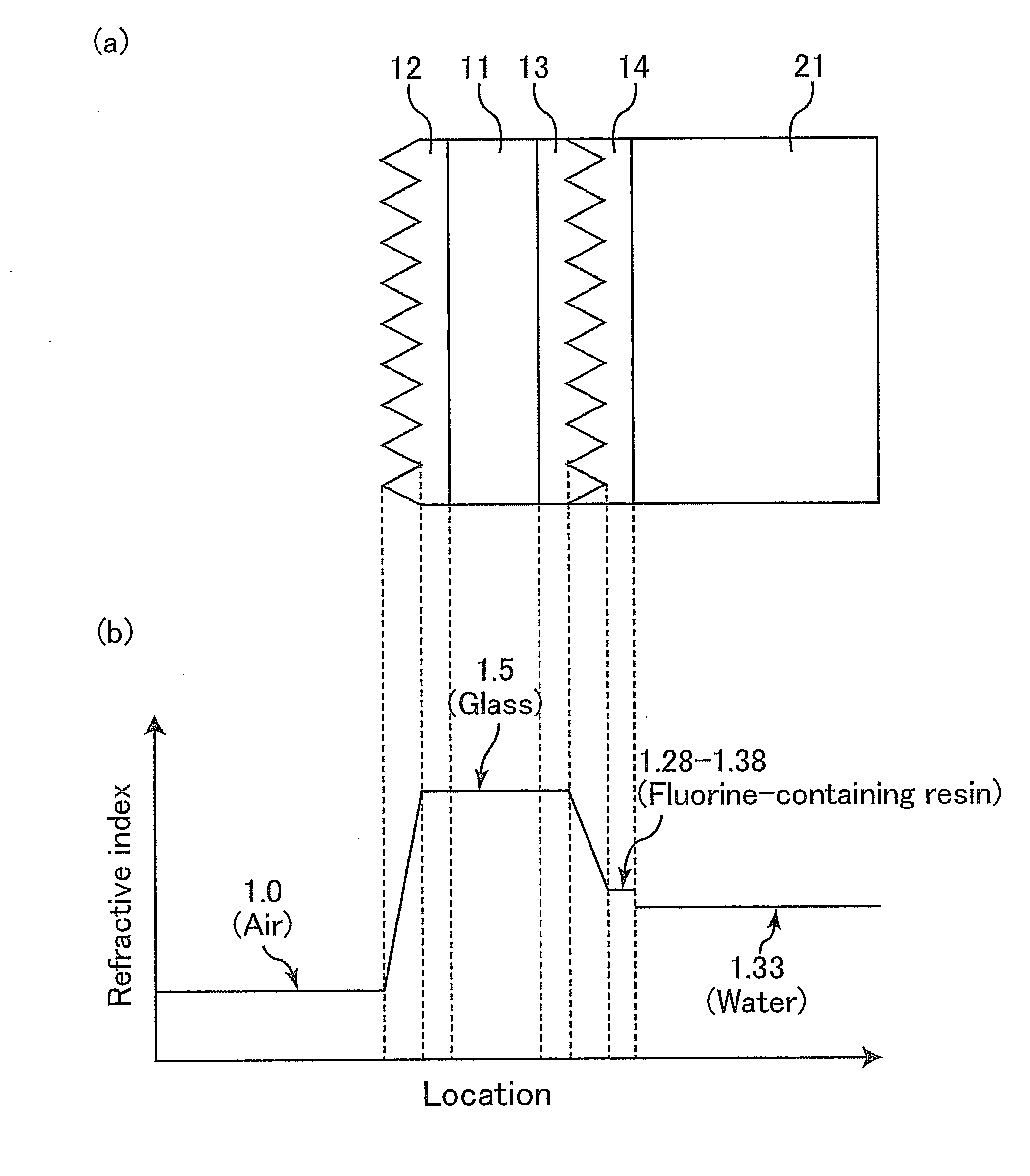
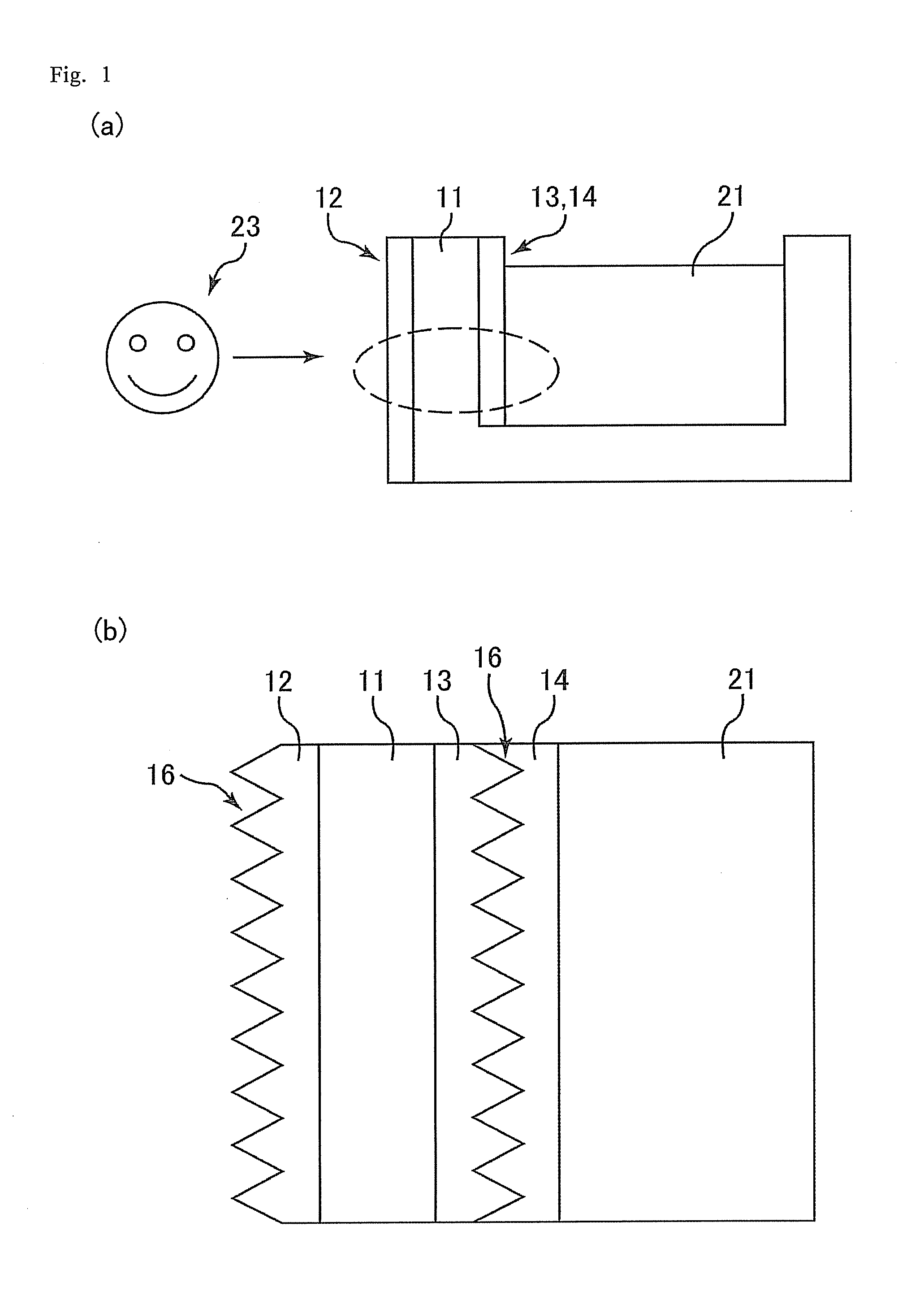
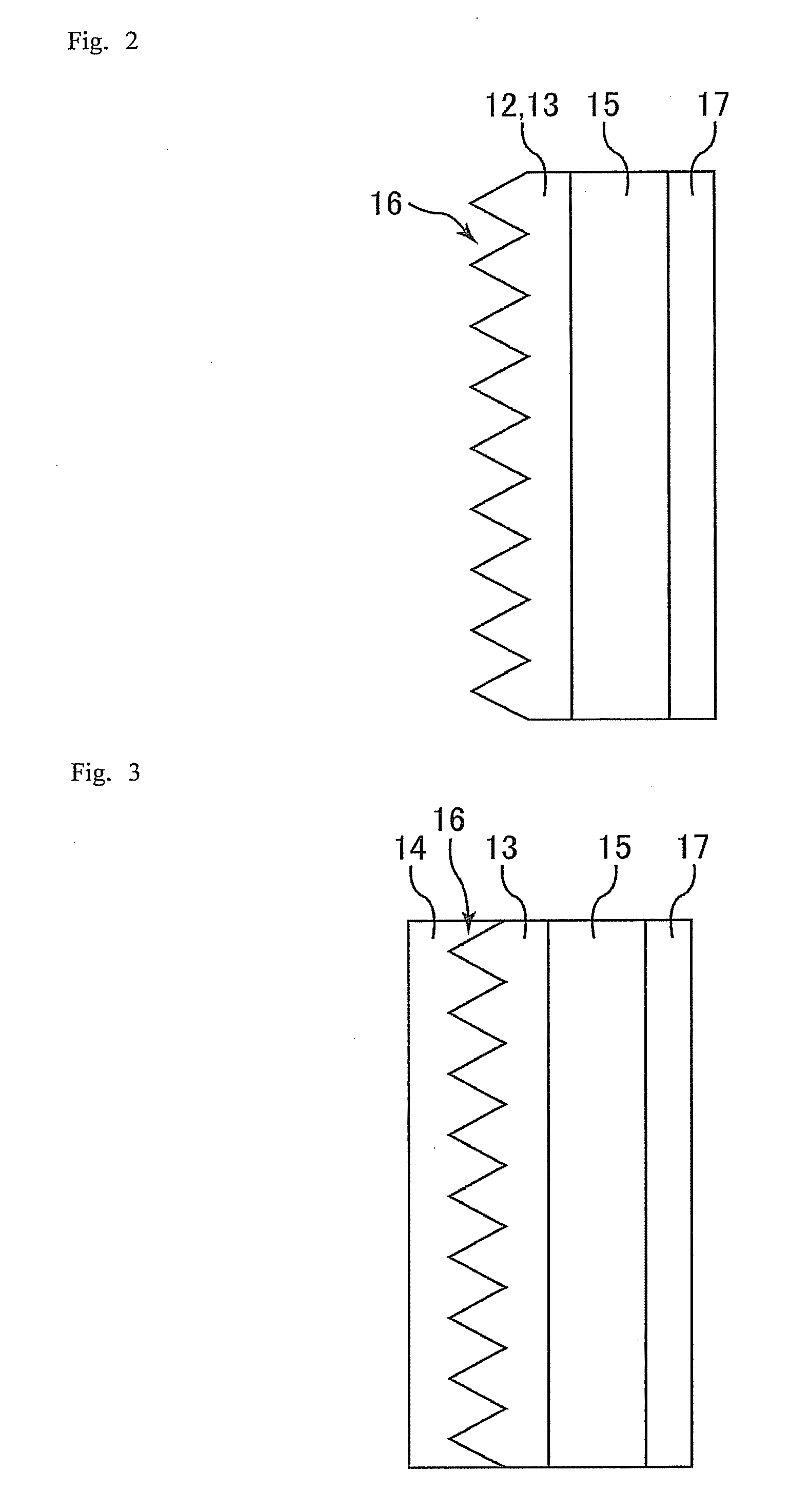
[0151]FIG. 1 is a schematic view showing a liquid tank of Example 1. FIG. 1(a) is an overall cross-sectional view of the tank. FIG. 1(b) is an enlarged view of a region (side surface) surrounded by the broken line of FIG. 1(a). FIG. 2 is a cross-sectional view schematically showing a moth-eye layer of the liquid tank of Example 1. FIG. 3 is a cross-sectional view schematically showing the moth-eye layer and a protective layer in the liquid tank of Example 1.

[0152]The present Example relates to an embodiment in which the liquid tank of the present invention is used as a water tank. The water tank of the present Example has a multi-layer structure, as shown in FIG. 1, composed of: a transparent wall 11 constituting a container storing a content liquid, or water 21; a moth-eye layer (moth-eye film) 12 attached to the external surface (hereinafter, also referred to as an “A surface”) of the transparent wall 11, which faces an observer 23; a moth-eye layer (moth-eye film) 13 attached to ...


PUM

PropertyMeasurementUnit
refractive indexaaaaaaaaaa

Abstract

A liquid tank, a viewing device for under-liquid observation, and an optical film are disclosed, each excellent in visibility and durability and being easy to clean. In at least one embodiment of the present invention is directed to a liquid tank having a transparent wall, including, on an internal surface of the wall, a first moth-eye layer having a moth-eye structure, and a protective layer covering the moth-eye structure, in this order from the wall side, and preferably, further including, on an external surface of the wall, a second moth-eye layer having a moth-eye structure, and the second moth-eye layer being disposed in a region facing the first moth-eye layer.

Description

TECHNICAL FIELD[0001]The present invention relates to liquid tanks, viewing devices for under-liquid observation, and optical films. More particularly, the present invention relates to: a liquid tank such as an aquarium tank and a tank with a liquid volume meter, suitably used as a container the inside of which is viewed through a transparent wall; a viewing device for under-liquid observation suitably used as a viewing device for underwater observation; and an optical film for the liquid tank or the viewing device.BACKGROUND ART[0002]The liquid tank includes an aquarium or observation container, and particularly tanks for raising and breeding fishes and the like thereinside are common. Such tanks are usually composed of a transparent material. In an aquarium tank containing water 21 as shown in FIG. 9, for example, ambient light is reflected on the external and internal (outer and inner surfaces) of an observer-side transparent plate (the transparent wall 11), and this makes it dif...

Claims


Application Information

Patent Timeline
Patent Type & Authority Applications(United States)
IPC IPC(8): G02B1/11
CPCA01K63/003G02B1/118G02B1/105G01F23/02G02B1/14
Inventor YAMADA, NOBUAKI
Owner SHARP KK
Why Eureka
Try Eureka