
Failure diagnostic apparatus and method of strong of storing failure information

a diagnostic apparatus and failure technology, applied in the field of failure diagnostic equipment and a method of storing information failure, can solve the problem of not being able to determine whether the dtc was stored, and achieve the effect of easy determination

Active Publication Date: 2010-11-18
TOYOTA JIDOSHA KK
View PDF2 Cites 9 Cited by
  • Summary
  • Abstract
  • Description
  • Claims
  • Application Information

AI Technical Summary

Benefits of technology

[0010]The invention provides a failure diagnostic apparatus that easily determines the environment in which the condition of a vehicle is examined.
[0015]Thus, the invention provides the failure diagnostic apparatus that easily determines the environment in which the condition of the vehicle is examined.

Problems solved by technology

In this case, when the DTC is retrieved using the scan tool, it cannot be determined whether the DTC was stored due to a failure that occurred when the vehicle was manufactured at the factory, or due to a failure that occurred when a driver used the vehicle.

Method used


Image

  • Failure diagnostic apparatus and method of strong of storing failure information
  • Failure diagnostic apparatus and method of strong of storing failure information
  • Failure diagnostic apparatus and method of strong of storing failure information

Examples


Embodiment Construction

[0020]Hereinafter, each of embodiments of the invention will be described with reference to the accompanying drawings.

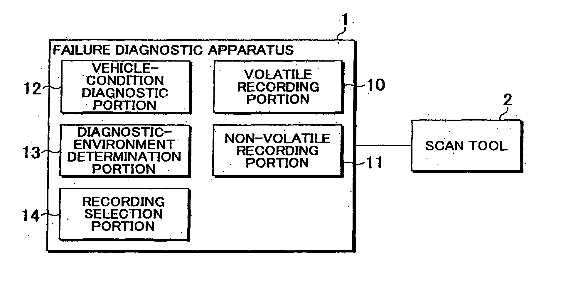
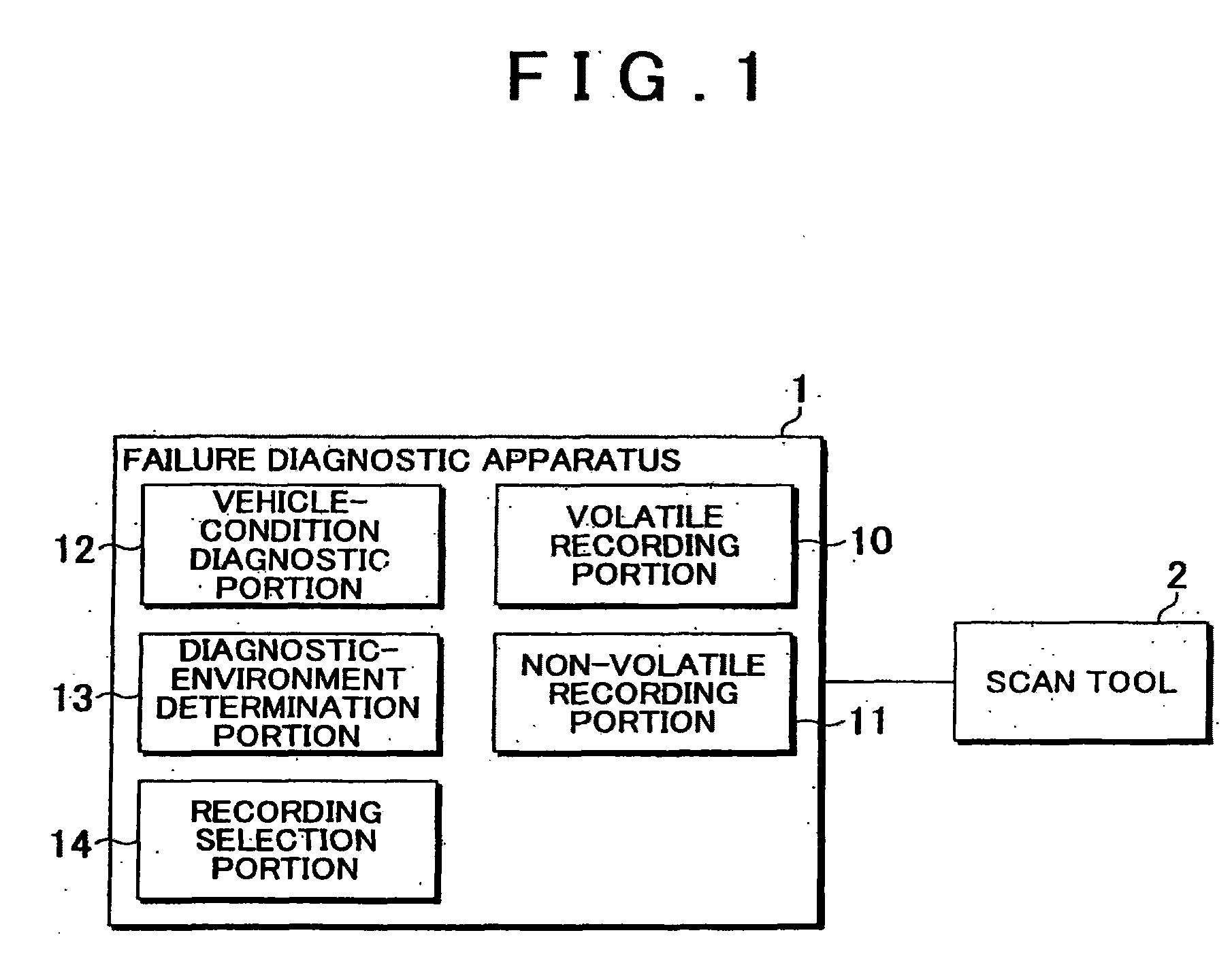
[0021]FIG. 1 shows an example configuration of a failure diagnostic apparatus. The failure diagnostic apparatus 1 includes a volatile storage portion 10, a non-volatile storage portion 11, a vehicle-condition diagnostic portion 12, a diagnostic-environment determination portion 13, and a storage selection portion 14. The failure diagnostic apparatus is connected to a scan tool 2 via a communication line such as CAN (Controller Area Network).

[0022]The failure diagnostic apparatus 1 may be provided in at least one ECU. Alternatively, the failure diagnostic apparatus 1 may be independent of any ECU, and may control at least one ECU via the communication line such as CAN.

[0023]In the volatile storage portion 10, information about a failure or an abnormality that occurs in a vehicle (hereinafter, the information will be referred to as “failure information”) is temporarily...


PUM


Abstract

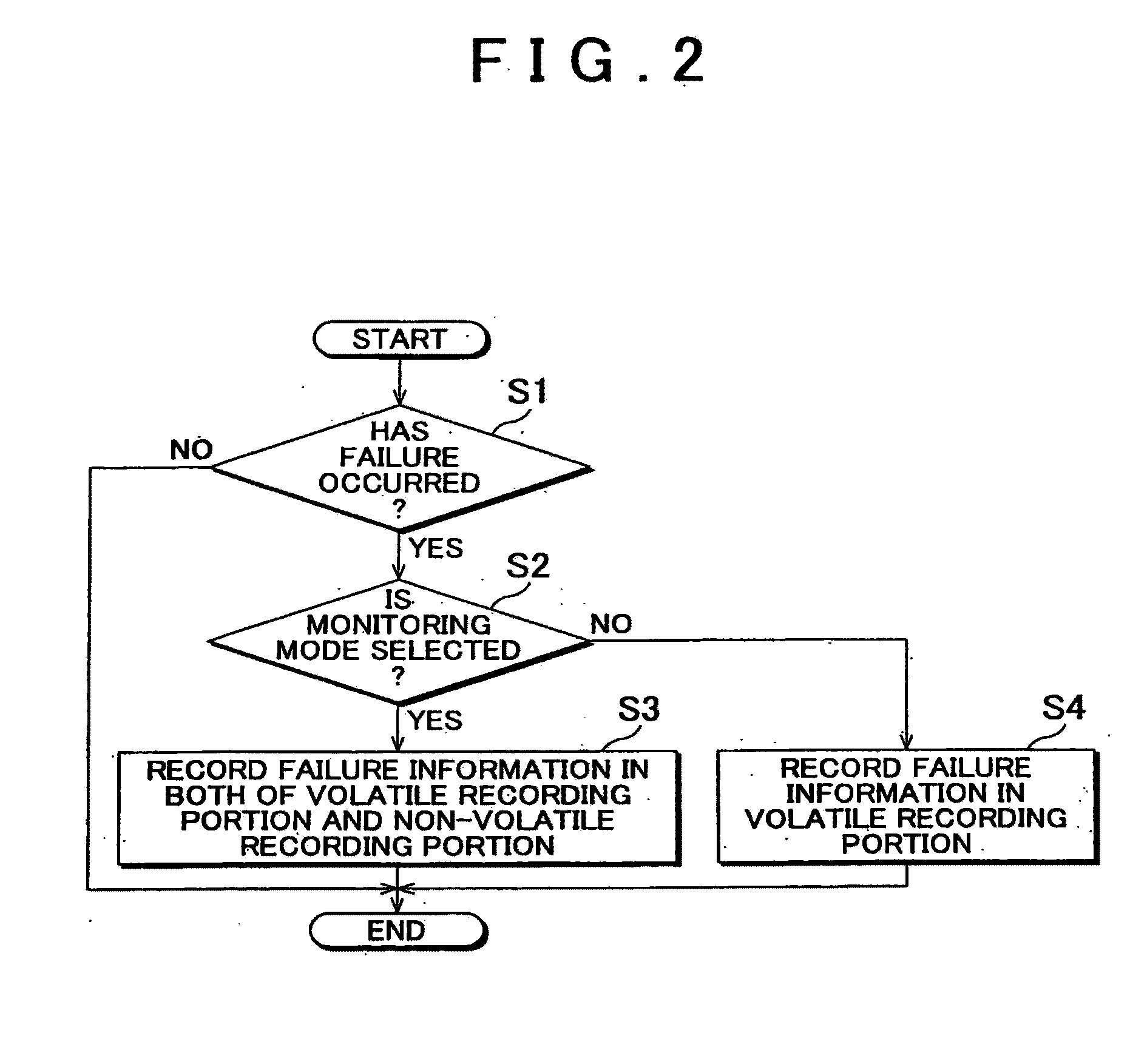
A failure diagnostic apparatus determines the environment in which the condition of a vehicle is examined and selects an appropriate storage location for information regarding the condition of the vehicle. In particular, the failure diagnostic apparatus includes a vehicle-condition diagnostic portion, a plurality of failure-information storage portions, a diagnostic-environment determination portion, and a storage selection portion. When the vehicle-condition diagnostic portion determines that a failure has occurred, the diagnostic-environment determination portion determines the environment in which the condition of the vehicle is examined. Then, based on the diagnostic environment determined by the diagnostic-environment determination portion, the storage selection portion selects at least one storage portion of the plurality of failure-information storage portions to store information regarding the failure.

Description

INCORPORATION BY REFERENCE[0001]The disclosure of Japanese Patent Application No. 2006-26228 filed on Feb. 2, 2006 including the specification, drawings and abstract is incorporated herein by reference in its entirety.BACKGROUND OF THE INVENTION[0002]1. Field of the Invention[0003]The invention relates to a failure diagnostic apparatus and a method of storing information failure. More particularly, the invention relates to a failure diagnostic apparatus and a method of storing failure information that easily determine the environment in which the condition of a vehicle is examined.[0004]2. Description of the Related Art[0005]Recently, it has been made mandatory to provide an On-Board Diagnostic-II (hereinafter, referred to as “OBD-II”) system in vehicles such as automobiles, to prevent air pollution. The OBD-II system provides a warning to a driver if a failure occurs in an exhaust gas control device. In the OBD-II system, information regarding a failure is stored in non-volatile me...

Claims


Application Information

Patent Timeline
Patent Type & Authority Applications(United States)
IPC IPC(8): G01M17/00G06F19/00B60R16/02G01M17/007
CPCG05B23/0264G07C2205/02G07C5/085G07C5/0808
Inventor MOROZUMI, HIROKI
Owner TOYOTA JIDOSHA KK
Learn More