
Computer system and method of controlling computer system

a computer system and computer system technology, applied in the field of computer systems, can solve the problems of affecting the next interrupt process, the inability to execute the lower priority interrupt process, and the inability to meet the run time constraints, so as to achieve the effect of disabling other interrupts

Inactive Publication Date: 2010-11-18
IBM CORP
View PDF38 Cites 9 Cited by
  • Summary
  • Abstract
  • Description
  • Claims
  • Application Information

AI Technical Summary

Benefits of technology

The present invention achieves atomicity in an embedded system by preventing interrupts from being influenced by other instructions. This is achieved by changing the configuration of the CPU so as to impart extended functions to a CALL instruction and a software interrupt instruction. The invention also includes a computer system with an interrupt mask register and a means for designating and disabling interrupts. The invention modifies the CPU architecture to allow for direct changes to the interrupt mask register based on the decoding result of the CPU instruction decoder. The invention achieves atomicity by allowing a single instruction to concurrently execute a call of a process and a value change of the interrupt mask register, and disabling other interrupts during execution of the single instruction.

Problems solved by technology

Inappropriate priority orders may cause another interrupt process to come in during execution of processes under the run time constraints, and thus make it more difficult to meet the run time constraints.
However, a lower priority interrupt process cannot be executed unless a value in the interrupt mask register is changed to a lower value.
However, the method has a problem of sometimes allowing another interrupt process to come in between the call instruction and the instruction to change the content of the interrupt mask register, because of the incapability of masking such interrupt instruction.
Consequently, the next interrupt process cannot be prevented from being influenced by another interrupt process.
However, the method has a problem that the execution takes a long time due to utilization of a peripheral device.
Even these prior art documents, however, neither suggest nor disclose any technique which prevents influence from another interrupt while a value of an interrupt vector is changed.
Without such a technique, numerous interrupt patterns may occur when control is passed from a higher priority interrupt process to a lower priority interrupt process.
Designing a program whose proper operation is guaranteed for all of the interrupt patterns is difficult in the program design phase based on the conventional techniques such as those described in these prior art documents.
Furthermore, it is more difficult to create, in the program test phase, test cases necessary for causing all of the possible interrupt patterns that can occur when control is passed from a higher priority interrupt process to a lower priority interrupt process.

Method used


Image

  • Computer system and method of controlling computer system
  • Computer system and method of controlling computer system
  • Computer system and method of controlling computer system

Examples


Embodiment Construction

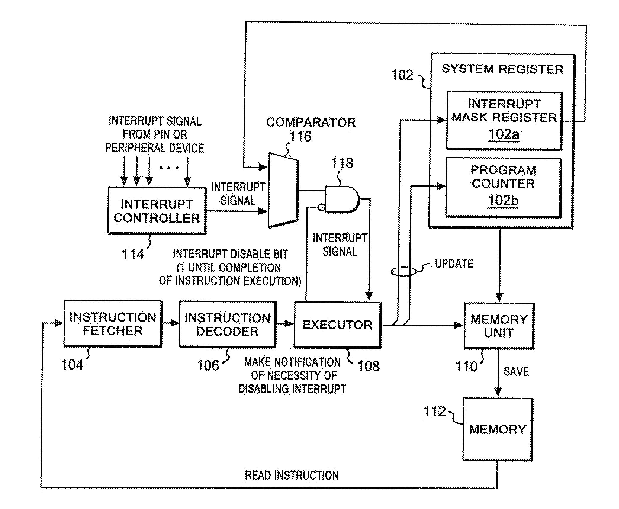
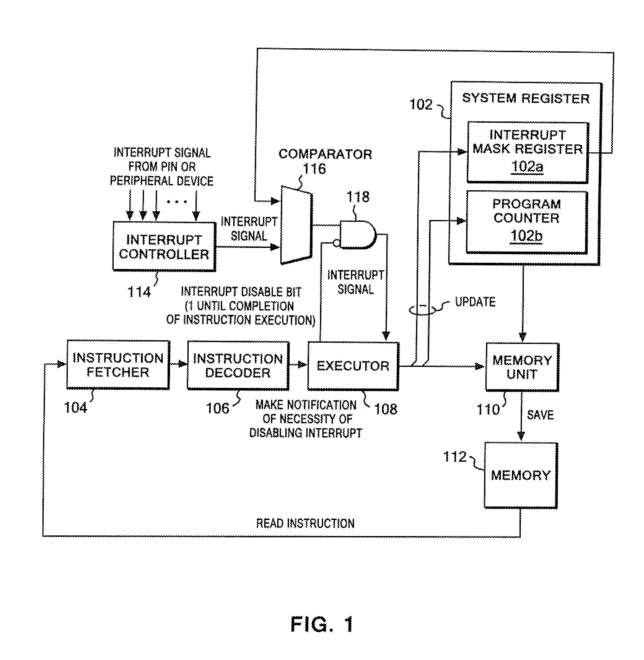
[0032]A configuration and processes of an embodiment of the present invention will be described below with reference to the drawings. In the following description, unless otherwise stated, same elements will be denoted by same reference numerals throughout the drawings. It should be understood that the configuration and processes described here are merely shown as one embodiment, and are not intended to limit the technical scope of the present invention to this embodiment.

[0033]FIG. 1 is a block diagram of a hardware configuration used for implementing the present invention. The configuration in FIG. 1 shows architecture of a typical CPU, and includes: a system register 102; an instruction fetcher 104 that fetches an instruction from a memory; an instruction decoder 106 that interprets the fetched instruction; and an executor 108 that executes the instruction interpreted by the instruction decoder 106.

[0034]The system register 102 consists of dedicated registers, such as an interrup...


PUM


Abstract

CPU architecture is modified so that content of the interrupt mask register can be changed directly based on a decoding result of an instruction decoder of a CPU. Such modification does not require a great deal of labor in changing a CPU design. In addition, an extended CALL instruction and an extended software interrupt instruction are added to the CPU, and each of the extended CALL instruction and the extended software interrupt instruction additionally has a function of changing the value of the interrupt mask register. Atomicity is achieved by: allowing such a single instruction to concurrently execute a call of a process and a value change of the interrupt mask register; and disabling other interrupts during execution of the single instruction.

Description

CROSS REFERENCE TO RELATED APPLICATION[0001]This application claims priority under 35 U.S.C. §119 from Japanese Patent Application No. 2009117642 filed May 14, 2009, the entire contents of which are incorporated by reference herein.BACKGROUND OF THE INVENTION[0002]1. Field of the Invention[0003]The present invention relates to a computer system. More particularly, the present invention relates to an instruction controller and interrupt control method that are used in an embedded system.[0004]2. Description of the Related Art[0005]In recent years, embedded systems have been used in every field in society, and have been taking important roles. Specifically, the embedded systems are used in a wide variety of fields such as digital cameras, mobile phones, DVD players, robots, flight control systems, fuel injection systems and automatic brake systems of automobiles.[0006]A conventional general definition of an embedded system is a computer system including hardware and software combined ...

Claims


Application Information

Patent Timeline
Patent Type & Authority Applications(United States)
IPC IPC(8): G06F13/24
CPCG06F13/24
Inventor KATAOKA, MASAKIKOMATSU, HIDEAKI
Owner IBM CORP
Learn More