Fast domain switch and error recovery in a secure CPU architecture

Inactive Publication Date: 2000-01-11
BULL HN INFORMATION SYST INC
View PDF5 Cites 7 Cited by
  • Summary
  • Abstract
  • Description
  • Claims
  • Application Information

AI Technical Summary

Benefits of technology

Briefly, these and other objects of the invention are achieved, in a CPU having data manipulation circuitry including a plurality of registers comprising a register bank, by employing first and second serially oriented safestore buffers. At suitable times during the processing of information by the data manipulation circuitry, a copy of the instantaneous contents of the register bank is transferred into the first safestore buffer. After a brief delay, a copy of the instantaneous contents of the first safestore buffer is transferred into the second safestore buffer. If a call for a domain change is sensed or, under certain conditions, if a fault (itself a type of call for a domain change) in the CPU is sensed, the first safestore buffer is loaded from the second safestore buffer rather than from the register bank. Later, if a restart of the interrupted process is undertaken and the restoration of the register bank is directed to be taken fro

Problems solved by technology

Those skilled in the art are aware of certain drawbacks to the usual provision of safestore capability, which drawbacks directly adversely affect CPU performance.
Thus, as higher levels of CPU performance are sought, the performance penalty resulting from the incorporation of safestore techniques to enhance fault tolerance must be more closely considered.
The technique discussed above has several drawbacks that adversely affect CPU performance.
First, even for the execution of simple instructions during which the safestore operation can be interleaved intermediate other processes which do not use the result bus so as to cause no extra cycle time, some of the registers to be safestore

Method used


Image

  • Fast domain switch and error recovery in a secure CPU architecture
  • Fast domain switch and error recovery in a secure CPU architecture
  • Fast domain switch and error recovery in a secure CPU architecture

Examples


Embodiment Construction

)

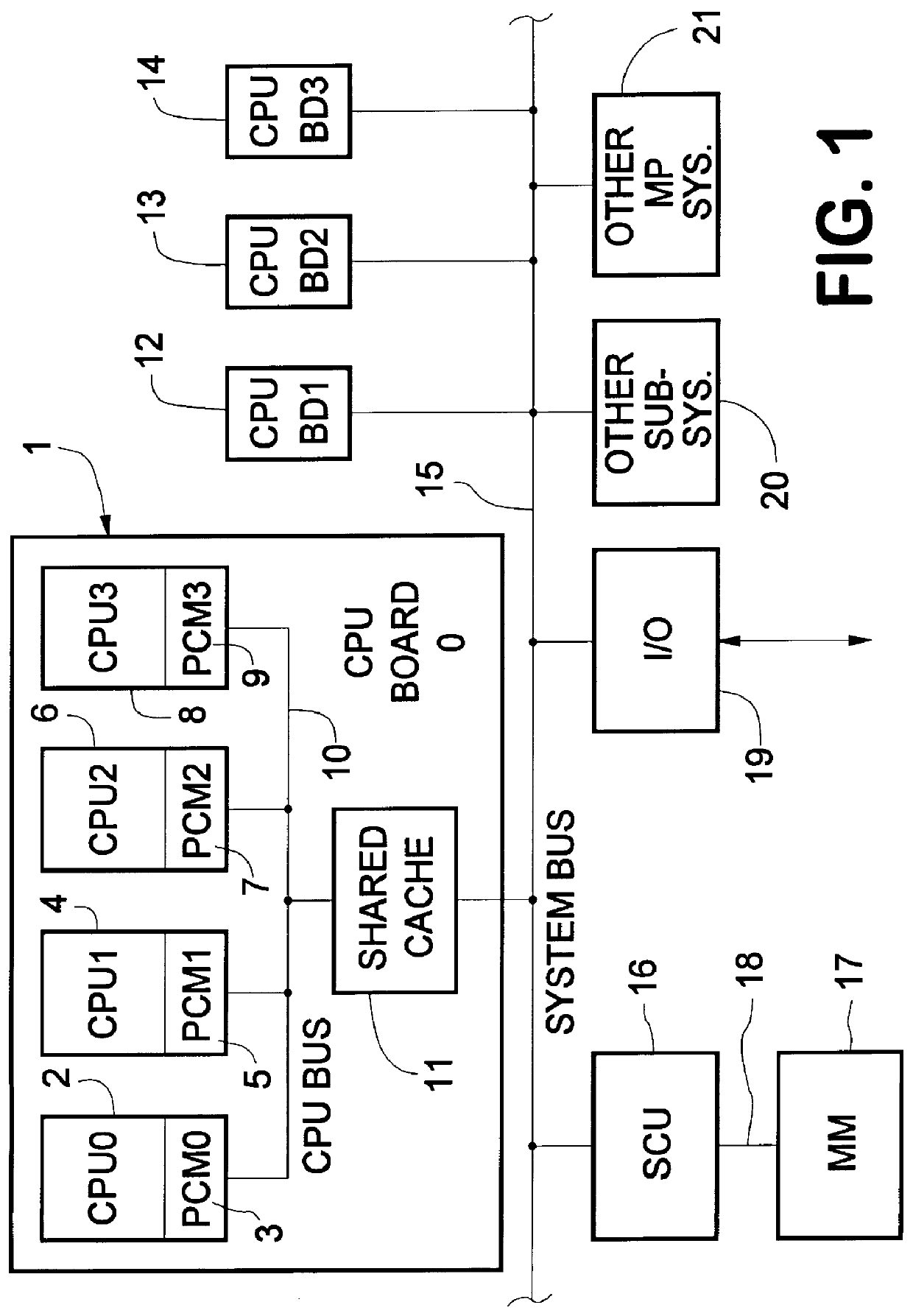
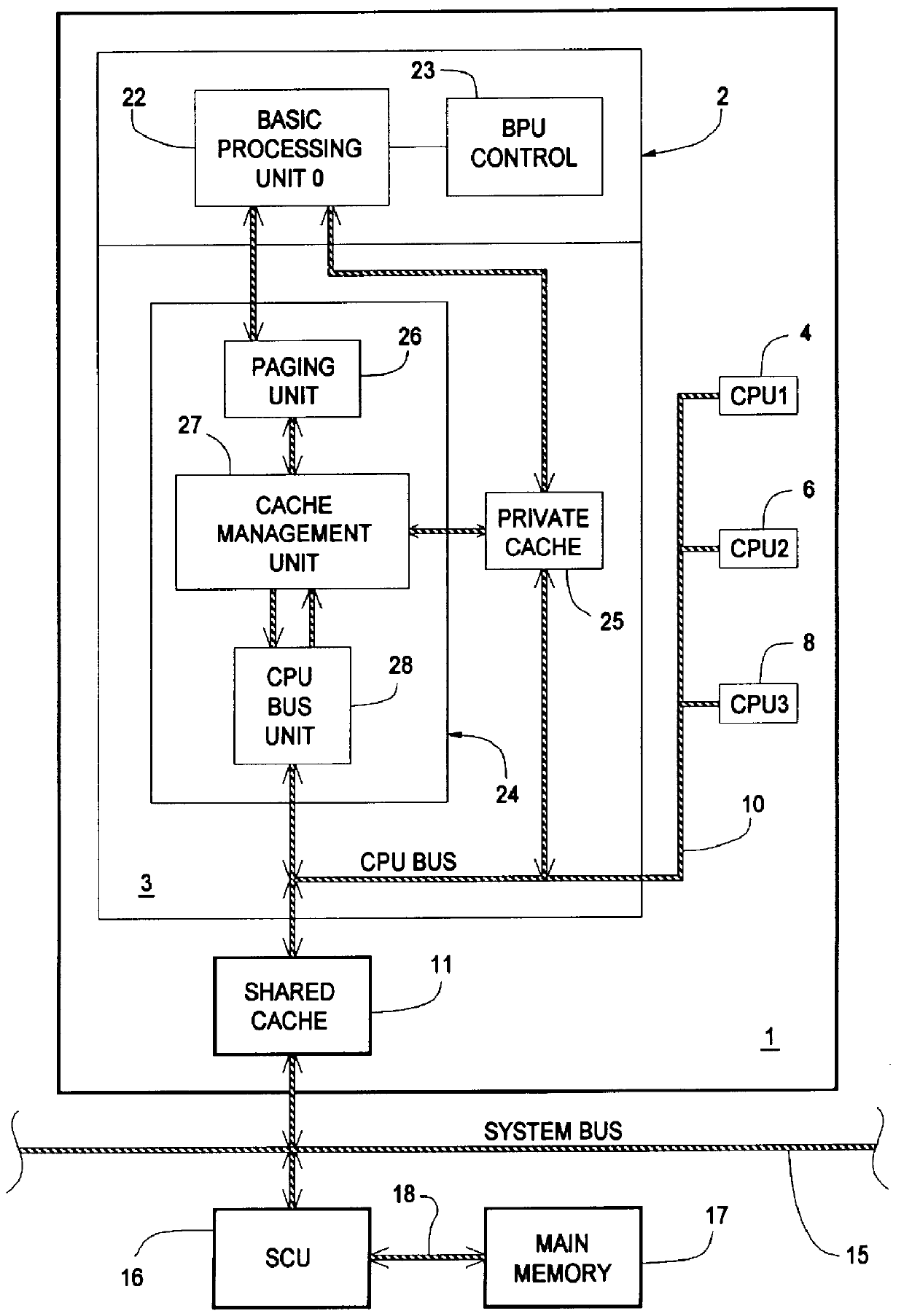
Attention is first directed to FIG. 1 which is a high level block diagram of an exemplary multiprocessor computer system incorporating the invention. A first CPU board (CPU Board "0") 1 includes four central processor units 2 (CPU "0"), 4 (CPU "1"), 6 (CPU "2"), 8 (CPU "3"). Each of the central processor units 2, 4, 6, 8 situated on the first CPU board 1 includes an integral private cache memory module, 3, 5, 7, 9, respectively. The private cache modules 3, 5, 7, 9 are each configured as "store into"; i.e., the results of each completed operation performed in the CPU are stored into the private cache. Each of the private cache modules 3, 5, 7, 9 on CPU Board "0" 1 interface with a CPU bus 10 for direct communications between the CPUs 2, 4, 6, 8.

In the exemplary system, there are three additional CPU boards 12 (CPU Board "1"), 13 (CPU Board "2") and 14 (CPU Board "3"), each of which is substantially identical to CPU board 1 although those skilled in the multiprocessor art will under...


PUM


Abstract

In order to gather, store temporarily and efficiently deliver safestore information in a CPU having data manipulation circuitry including a register bank, first and second serially oriented safestore buffers are employed. At suitable times during the processing of information, a copy of the instantaneous contents of the register bank is transferred into the first safestore buffer. After a brief delay, a copy of the first safestore buffer is transferred into the second safestore buffer. If a call for a domain change (which might include a process change or a fault) is sensed, a safestore frame is sent to cache, and the first safestore buffer is loaded from he second safestore buffer rather than from the register bank. Later, during a climb operation, if a restart of the interrupted process is undertaken and the restoration of the register bank is directed to be taken from the first safestore buffer, this source, rather than the safestore frame stored in cache, is employed to obtain a corresponding increase in the rate of restart. In one embodiment, the transfer of information between the register bank and the safestore buffers is carried out on a bit-by-bit basis to achieve additional flexibility of operation and also to conserve integrated circuit space.

Description

This invention relates to computer central processors and, more particularly, to the repetitive temporary storage of central processing register contents and other information in a safestore frame in order to facilitate recovery from a fault or transfer to another domain.As personal computers and workstations become more and more powerful, makers of mainframe computers have undertaken to provide features which cannot readily be matched by these smaller machines in order to stay viable in the marketplace. One such feature may be broadly referred to as fault tolerance which means the ability to withstand and promptly recover from hardware faults without the loss of crucial information. The central processing units of mainframe computers typically have error detection circuitry, and sometimes error recovery circuitry, built in at numerous information transfer points in the logic to detect and characterize any fault which might occur.The CPU(s) of a given mainframe computer comprises ma...

Claims


Application Information

Patent Timeline
IPC IPC(8): G06F11/14G06F9/38
CPCG06F9/3863G06F11/1405G06F11/1407
Inventor YODER, RONALD W.GUENTHNER, RUSSELL W.BUZBY, WAYNE R.
Owner BULL HN INFORMATION SYST INC
Why Eureka
Try Eureka