Magnetic Flapper Shock Absorber

a shock absorber and magnetic technology, applied in the direction of fluid removal, borehole/well accessories, construction, etc., can solve the problems of flapper or seat damage, serious damage, and both damage, and achieve the effect of dripping or eliminating shock loading

Active Publication Date: 2010-11-25
BAKER HUGHES INC
View PDF19 Cites 36 Cited by
  • Summary
  • Abstract
  • Description
  • Claims
  • Application Information

AI Technical Summary

Benefits of technology

[0004]A flapper in a subsurface safety valve has at least one magnet that comes in close proximity with another magnet mounted in a fixed position on the valve body. There is a fixed magnet on the body adjacent to the fully open and the fully closed positions of the flapper. In each case like poles on the flapper magnet and the housing magnet come in close proximity as the flapper reaches its fully open and fully closed positions. The orientation of like poles adjacent each other creates a repelling force that damps or eliminates shock loading.

Problems solved by technology

In downhole applications and most particularly in valves where large pressure differentials can build in an instant as a valve member such as a flapper moves against a seat, there can be serious damage from the impact force that can be severe enough to deform the valve member or the mating seat.
In the case of subsurface safety valve flappers, when opened but more so when allowed to close, there is a risk of flapper or seat damage or damage to both from a severe impact loading.

Method used


Image

  • Magnetic Flapper Shock Absorber
  • Magnetic Flapper Shock Absorber
  • Magnetic Flapper Shock Absorber

Examples


Embodiment Construction

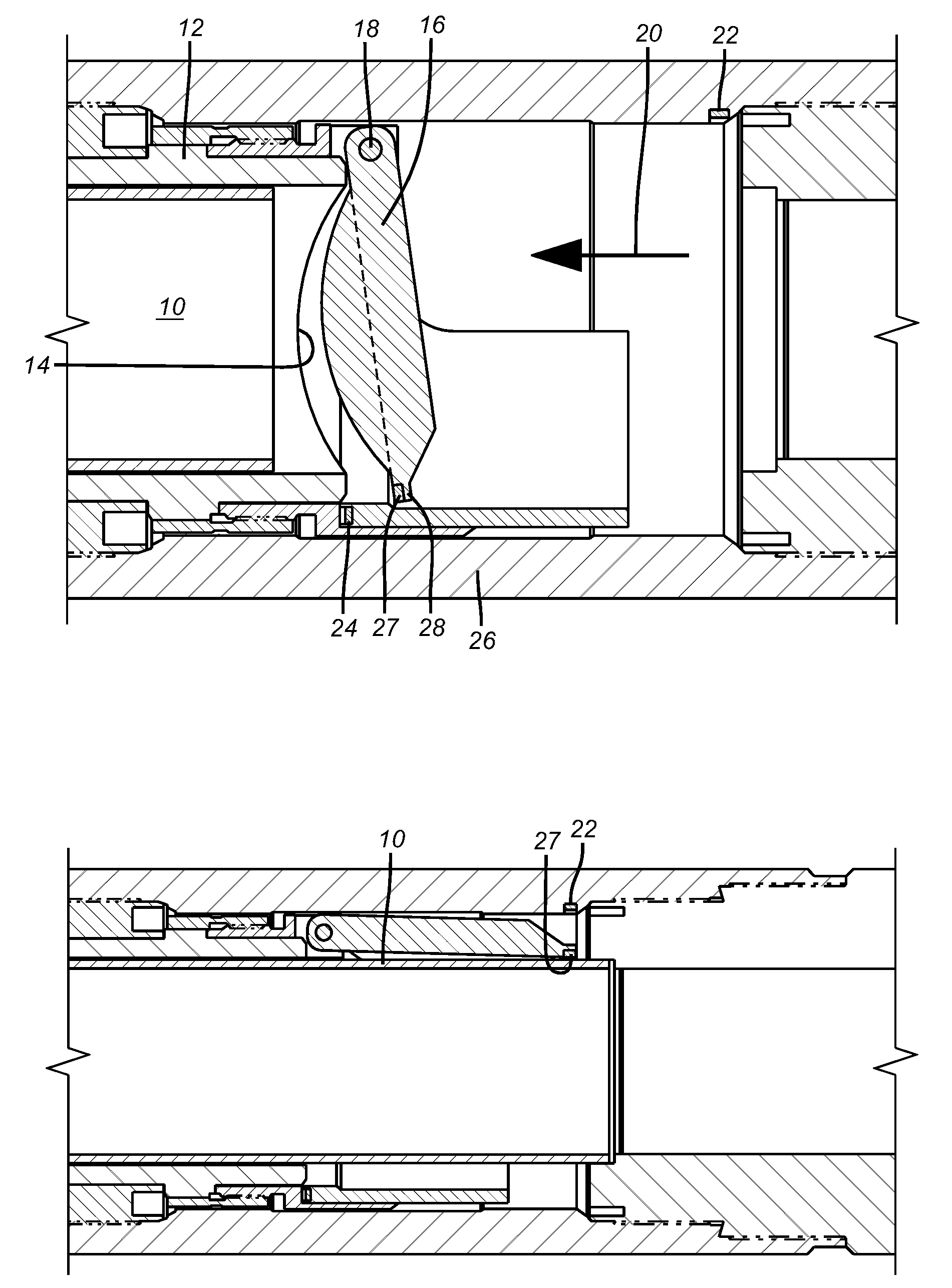
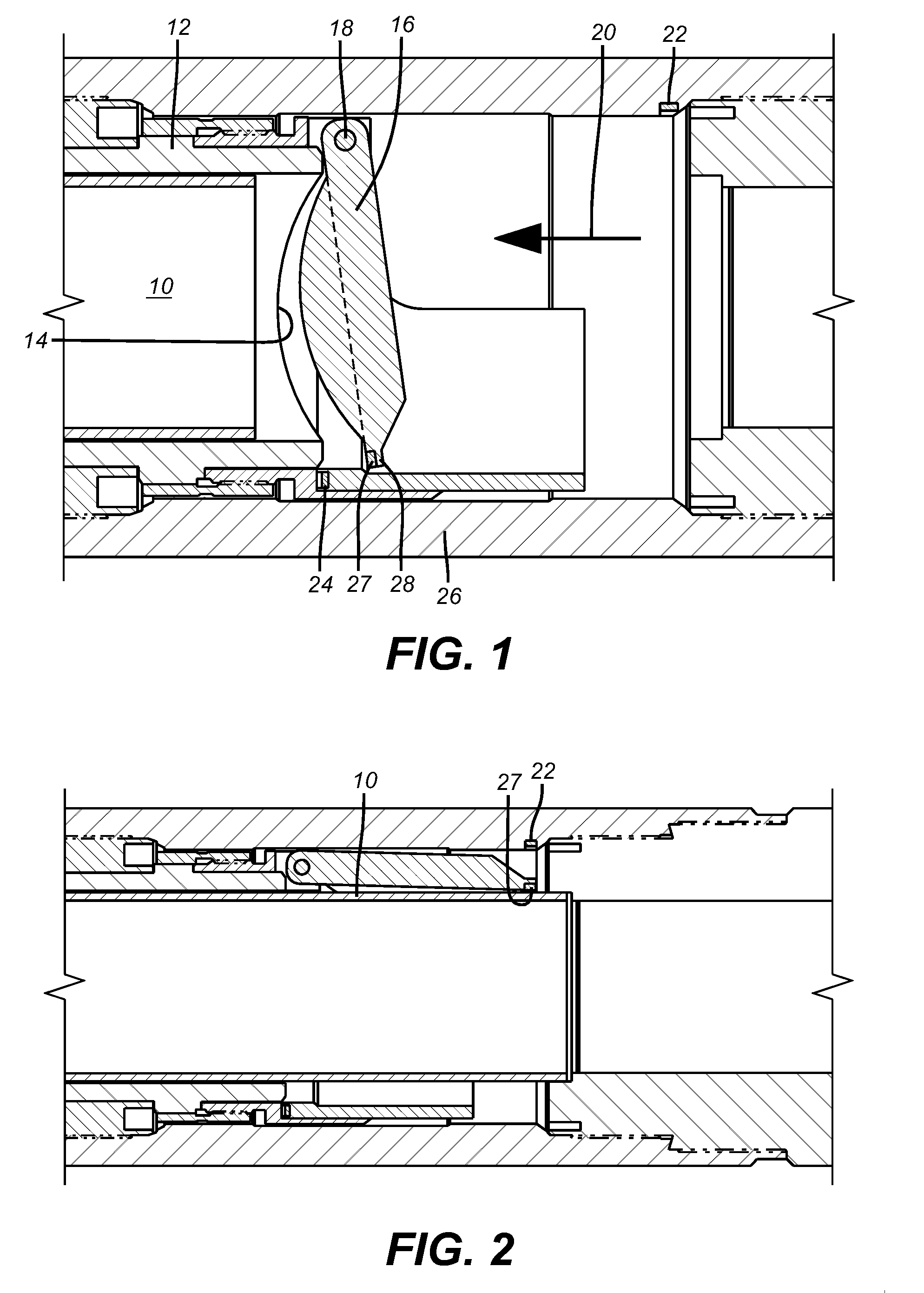
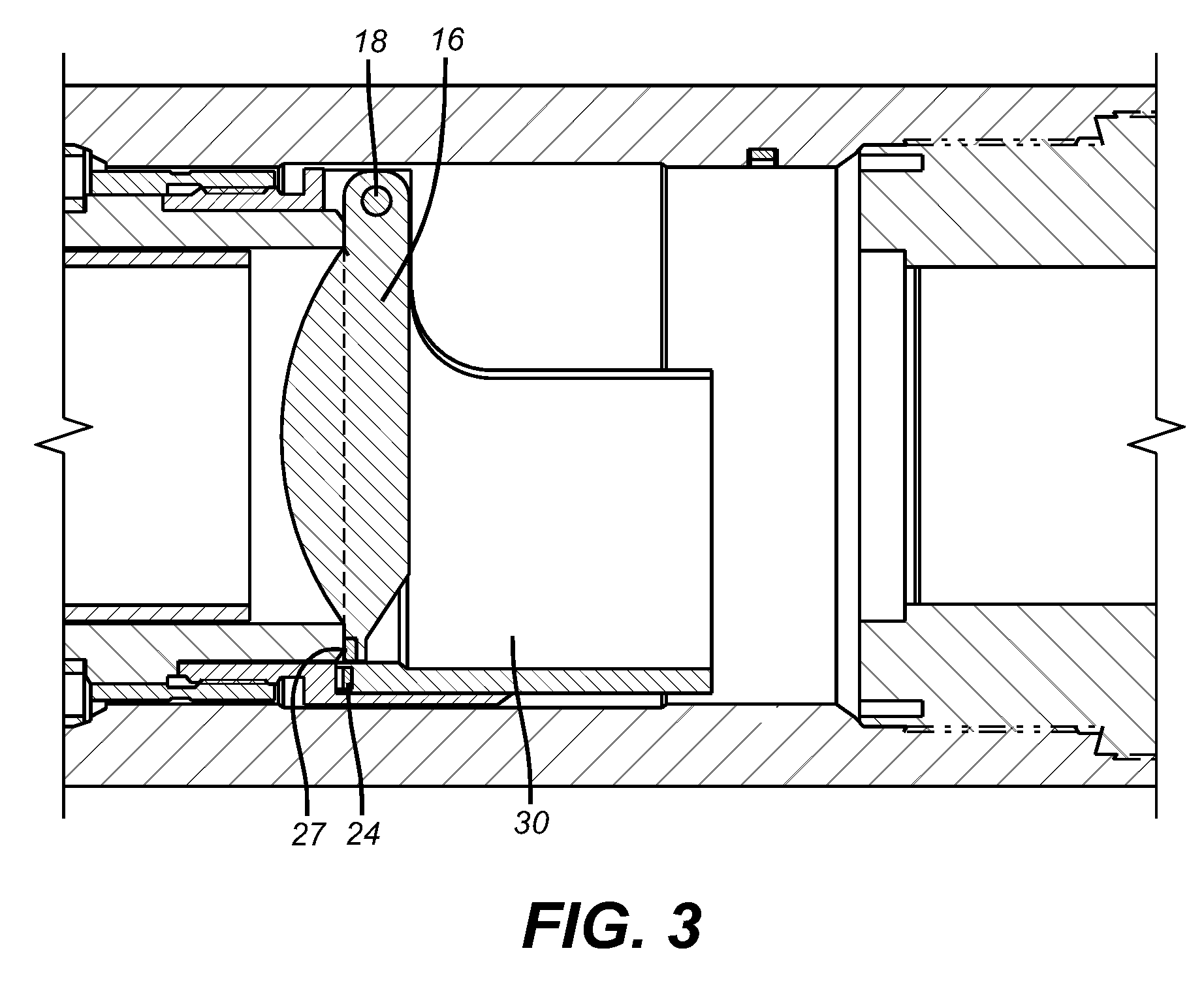
[0008]The basic structure of a downhole subsurface safety valve is known to those skilled in the art. Basically, a hydraulic control line runs from the surface to the valve to operate a piston that is biased against the applied pressure in the control line. Pressurizing the control line moves the piston which is linked for tandem movement with a flow tube 10. The flow tube 10 rides inside seat assembly 12 the lower end of which has a seat 14. A flapper 16 is pivoted at 18 and the pivot shaft can have a spring to bias the flapper 16 into the closed position of FIG. 3 when the pressure on the control line is removed and a closure spring pushes the piston in an opposed direction which has the effect of retracting the flow tube 10 at which point the spring on the pivot 18 initiates movement of the flapper 16 toward seat 14. The flow trying to come uphole as represented by arrow 20 helps to get the flapper 16 moving toward its seat 14. The seat 14 and the corresponding portion of the fla...


PUM


Abstract

A flapper in a subsurface safety valve has at least one magnet that comes in close proximity with another magnet mounted in a fixed position on the valve body. There is a fixed magnet on the body adjacent to the fully open and the fully closed positions of the flapper. In each case like poles on the flapper magnet and the housing magnet come in close proximity as the flapper reaches its fully open and fully closed positions. The orientation of like poles adjacent each other creates a repelling force that damps or eliminates shock loading.

Description

FIELD OF THE INVENTION[0001]The field of this invention is tools used in a subterranean formation that have a movable component that is subjected to shock loading and the use of a field to cushion impact loads and more particularly using a magnetic field to control shock loading on a flapper of a subsurface safety valve.BACKGROUND OF THE INVENTION[0002]Magnets have been used to act as dampeners such as in the context of exercise equipment as illustrated in U.S. Pat. No. 5,752,879. Magnets have been used in fluid flow systems to hold a position of a moving component such as for example in an open or a closed position. Illustrative of a gas line and a medical device application are U.S. Pat. No. 5,209,454 and U.S. Pat. No. 5,970,801. In a similar vein is U.S. Pat. No. 7,527,069. The use of magnets to control the fixation of a movable member in a level control application is seen in U.S. Pat. No. 4,436,109. These disparate applications seek to use the force of a magnetic field for fixa...

Claims


Application Information

Patent Timeline
Patent Type & Authority Applications(United States)
IPC IPC(8): E21B34/06
CPCE21B34/10E21B2034/005E21B34/14E21B2200/05
Inventor XU, RICHARD Y.
Owner BAKER HUGHES INC
Why Eureka
Try Eureka