Cutter tensioning and loosening device based on cam-ratchet mechanism

A ratchet mechanism and cam technology, applied in positioning devices, manufacturing tools, metal processing mechanical parts, etc., can solve problems such as bearing failure, unbalanced movement of the fork position, and reduced spindle running quality.

Active Publication Date: 2022-04-29
HENAN UNIVERSITY OF TECHNOLOGY
View PDF4 Cites 0 Cited by
  • Summary
  • Abstract
  • Description
  • Claims
  • Application Information

AI Technical Summary

Problems solved by technology

During the tool change (knife punching) process of the current vertical or horizontal machining center, the following phenomena generally exist: (1) The shift fork of the tool change mechanism collides with the knife punching block, which generates an impact load and transmits it to the spindle mandrel and the front and rear of the spindle End support bearing (especially the rear end bearing); (2) There is a space for the shift fork to move on the spindle tool rod, causing the position of the shift fork to move and generate dynamic imbalance; (3) When changing the tool (tightening and loosening the tool) During the process, the spindle bearing always bears the axial force of the broach
The multiple tool change actions, impact load and axial force of the broach in the machining center degrade the running quality of the spindle, and the bearing fails in advance, which greatly reduces the service life of the bearing and even the spindle. It is a common difficult problem in the field of machining center manufacturing.

Method used


Image

  • Cutter tensioning and loosening device based on cam-ratchet mechanism
  • Cutter tensioning and loosening device based on cam-ratchet mechanism
  • Cutter tensioning and loosening device based on cam-ratchet mechanism

Examples


Embodiment Construction

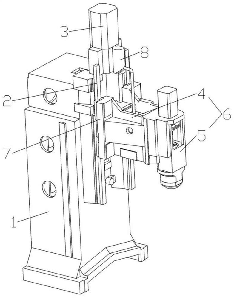
[0023] Below in conjunction with accompanying drawing and specific embodiment the present invention is described in further detail:

[0024] The specific embodiment of the tool tightening and loosening device based on the cam-ratchet mechanism of the present invention, such as Figure 1 to Figure 5 As shown, it includes a column 1 on which there are two slide rails 2 extending vertically and arranged in parallel and spaced apart. A screw rod is installed at a position between the two slide rails 2 of the column 1, and the axis of the screw rod extends vertically. The upper end and the lower end of the screw are respectively installed on the column 1 through bearing rotation, the upper end of the screw protrudes to the upper side of the bearing, the drive motor 3 is fixedly installed on the column 1, and the output shaft of the drive motor 3 is fixed to the upper end of the screw through a coupling connect. After the drive motor 3 starts, the drive screw rotates.

[0025] In...


PUM


Abstract

The invention relates to a cutter tensioning and loosening device based on a cam-ratchet mechanism. The cutter tensioning and loosening device based on the cam-ratchet mechanism comprises a stand column, a spindle box moving up and down is assembled on the stand column in a sliding mode, and a spindle assembly with the rotating axis extending in the vertical direction is rotationally assembled in the spindle box; the main shaft assembly comprises a main shaft, a lead screw, a ratchet wheel, a guide rod, a compression spring and a cutter claw, the main shaft is provided with a central through hole, the lead screw is installed on the upper side of the central through hole in a threaded mode, a fixed bearing coaxial with the lead screw is installed in the central through hole, the ratchet wheel is fixedly connected with the fixed bearing, the ratchet wheel is connected to the lead screw in a threaded mode, and the guide rod is arranged on the guide rod. A communicating hole communicated with the ratchet wheel is formed in the outer wall of the main shaft, the guide rod is installed in a center through hole in the lower side of the lead screw in a guiding mode, and the cutter claw is connected to the lower end of the guide rod. The running quality of the main shaft is improved, the service life of the main shaft is prolonged, the reliability of the main shaft is improved, and the service life and the reliability of the bearing are improved.

Description

technical field [0001] The invention belongs to the technical field of machine tool auxiliary devices, and in particular relates to a tool tensioning and loosening device based on a cam-ratchet mechanism. Background technique [0002] In the field of mechanical manufacturing, the processing of a part requires the cooperation of multiple processes, and different types and sizes of tools are required to complete, so tool replacement is required. [0003] At present, the tool change principle of the tool tightening and loosening device in the machining center on the market is: the movement of the spindle box along the column (Z direction) is converted into the translation (Z direction) movement of the shift fork through the horizontal axis swing follower moving the cam mechanism, Drive the tool rod (Z direction) to move to realize the tool tightening and loosening. During the tool change (knife punching) process of the current vertical or horizontal machining center, the follo...

Claims


Application Information

Patent Timeline
Patent Type & Authority Applications(China)
IPC IPC(8): B23Q3/12B23Q3/157
CPCB23Q3/12B23Q3/157
Inventor 申会鹏张小彩丁浩张海博吴星辰张天宇
Owner HENAN UNIVERSITY OF TECHNOLOGY
Why Eureka
Try Eureka