Clamping device with a linking member

a technology of linking member and clamping device, which is applied in the direction of manufacturing tools, transportation and packaging, drawing boards, etc., to achieve the effect of simplifying the structure of the clamping device, reducing the speed of sliding, and being more stable of the second slide member

Active Publication Date: 2010-11-25
COMART CORP
View PDF8 Cites 44 Cited by
  • Summary
  • Abstract
  • Description
  • Claims
  • Application Information

AI Technical Summary

Benefits of technology

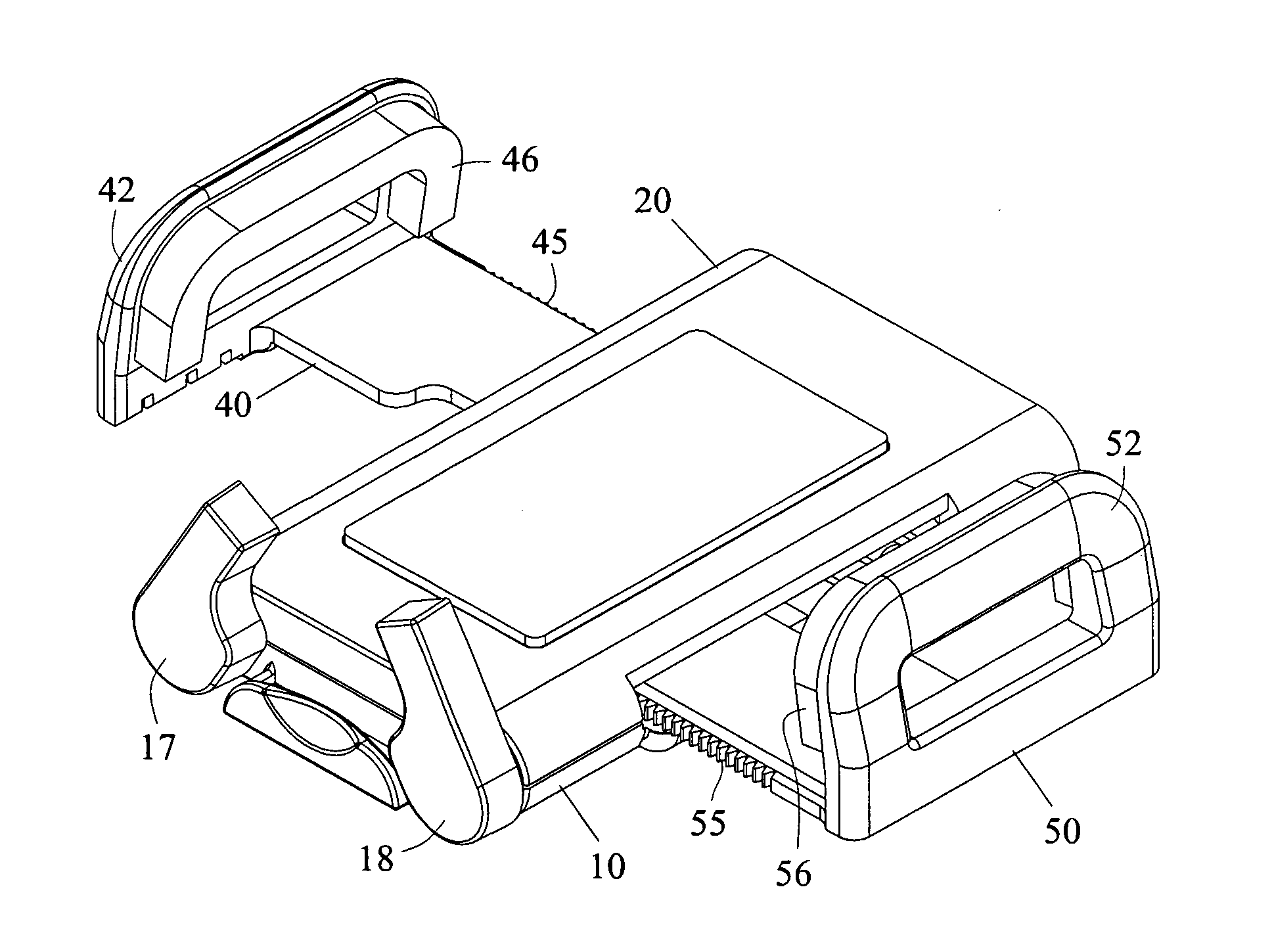
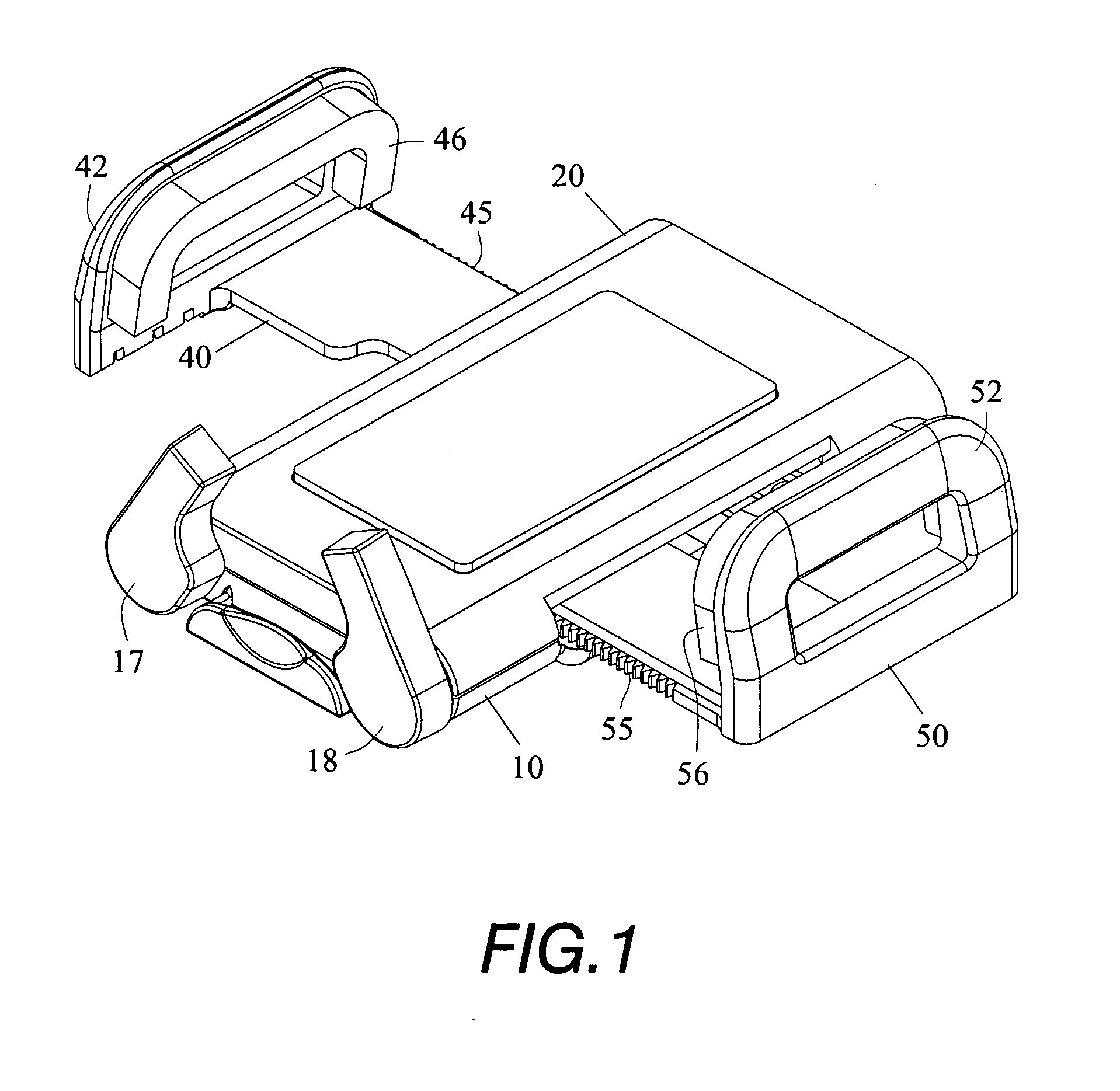
[0007]The effect of gain of the present invention is resided in getting rid of the restraining of the conventional clamping device in order to suit clamping other wider instruments, the present invention can slow down the speed of sliding of the first and the second slide members, and can make more stable of the second slide member during sliding to and fro.
[0008]Another effect of gain of the present invention is resided in that the linking member can be circular which is provided on and around its periphery with a set of positioning teeth, the positioning rack is provided to allow a positioning claw of an engaging member to engage therein for positioning, this can further simplify the structure of the clamping device.

Problems solved by technology

However, the structural features of the fork shaped link and the clamp seats will restrain the stroke of to and fro movement, i.e., the ranges that the clamp seats extend are restrained; and thereby when a user desires to clamping hold a wider instrument, it is wondered if such conventional clamping device is not suitable for use some times.

Method used


Image

  • Clamping device with a linking member
  • Clamping device with a linking member
  • Clamping device with a linking member

Examples


second embodiment

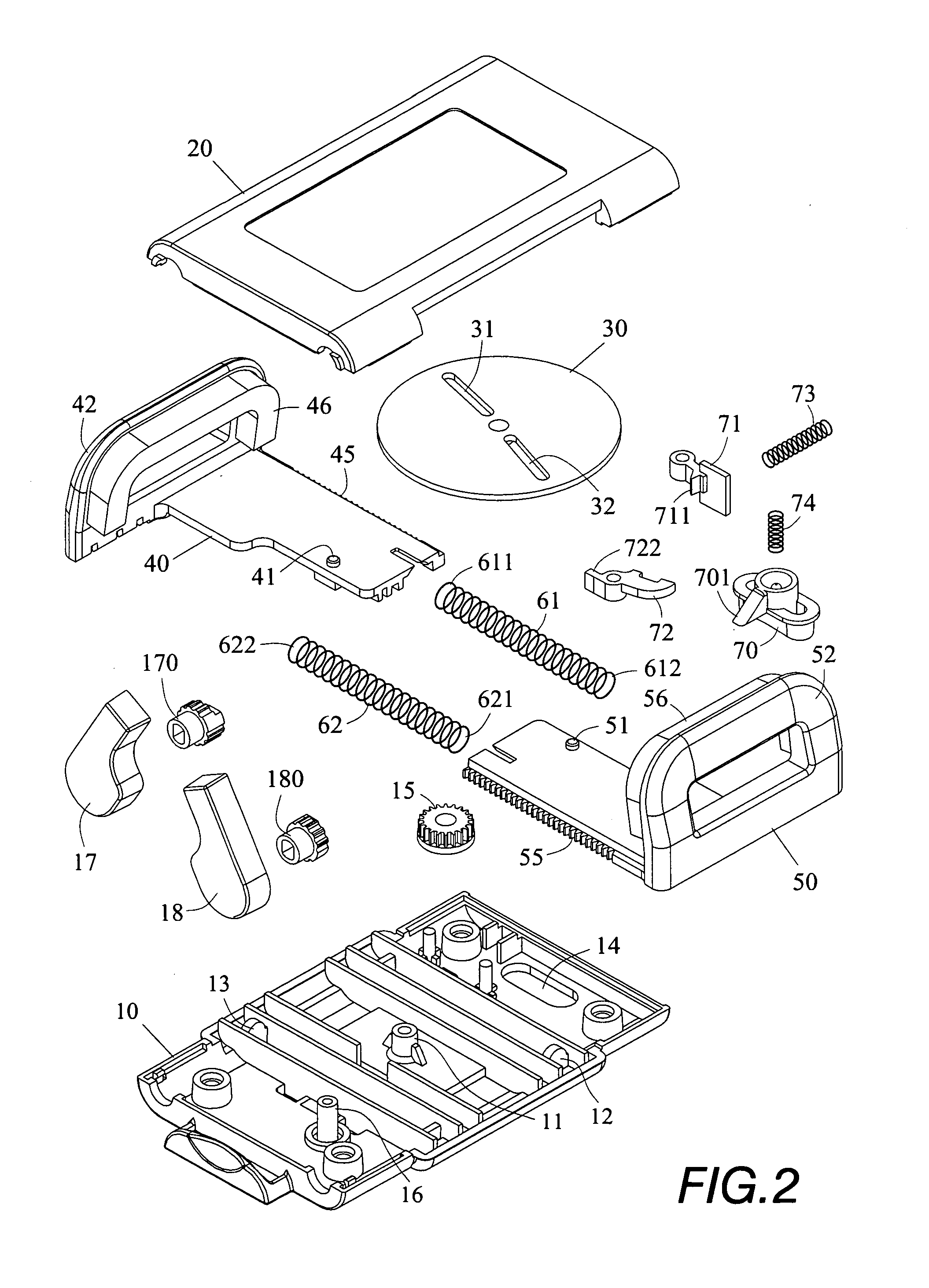
[0044]Referring to FIG. 9 showing the present invention, wherein the base 10 is pivotally provided with a second gear 19 in engaging with the first gear 15, a pivot axle 190 of the second gear 19 has damping oil, the siding speeds of the first and the second slide members 40, 50 can thus be retarded, and the second slide member 50 will be more stable during its to and fro sliding.

third embodiment

[0045]Referring to FIG. 10 showing the present invention, wherein the structure of the clamping device is further simplified, a linking member 30a provide on the base 10 is circular which has two guiding slits 31, 32; a positioning pin 41 of the first slide member 40 is extended through the guiding slit 31, and a positioning pin 51 of the second slide member 50 is extended through the guiding slit 32, the linking member 30a is provided on and around its periphery with a set of positioning teeth 33, the positioning claw 711 of the engaging member 71 can be pushed by the positioning spring 73 to engage in the set of positioning teeth 33; the first slide member 40 and the second slide member 50 can get the effect of one way positioning by means of the set of positioning teeth 33 and the positioning claw 711 of the engaging member 71; that is, when the first slide member 40 and the second slide member 50 slide inwards for restoration from their extending positions, the linking member 30...


PUM


Abstract

A clamping device with a linking member, the linking member is pivotally connected with a first and a second slide member, the slide members can be extended outwards and contracted inwards; wherein when deviation angles of two guide slits of the linking member are sharp angles, the first and the second slide members are at their initiate positions, and when deviation angles of two guide slits are obtuse angles, the first and the second slide members are at their extending positions.

Description

BACKGROUND OF THE INVENTION[0001]1. Field of the invention[0002]The present invention relates to a clamping device operated with a linking member, and especially to a clamping device with a linking member which is pivotally connected with a pair of slide members, thus the slide members can be extended outwards and contracted inwards.[0003]2. Description of the Prior Art[0004]A conventional technique which is a U.S. Pat. No. 5,903,645 titled “CLAMPING DEVICE FOR MOBILE PHONES” mainly has a fork shaped link integrally and pivotally connected at a center, the link has a left and a right end each pivotally connected with a clamp seat, the clamp seat is provided on its lateral side with slanting rack teeth, an elastic securing seat is disposed adjacent to the slanting rack teeth and has stop elements for projecting into the rack teeth; the clamp seat can only displace inwardly to be positioned in place; the securing seat has a slanting notch at its rear end, the slanting notch is provide...

Claims


Application Information

Patent Timeline
Patent Type & Authority Applications(United States)
IPC IPC(8): B25B5/06
CPCB60R11/0241B60R2011/0071B60R11/0258
Inventor WOODY, LIU
Owner COMART CORP
Why Eureka
Try Eureka