
Method and apparatus for forming a vehicle trim panel

a technology for forming trim panels and motor vehicles, which is applied in the direction of dough shaping, manufacturing tools, roofs, etc., can solve the problems of unattractive edges that are also susceptible to separating, and add time and cost, so as to increase the width of the finished edge, clean and aesthetically pleasing appearance, and add cost and/or time to the manufacturing process.

Active Publication Date: 2010-11-25
YANFENG CZECHIA AUTOMOTIVE INTERIOR SYST SRO
View PDF3 Cites 10 Cited by
  • Summary
  • Abstract
  • Description
  • Claims
  • Application Information

AI Technical Summary

Benefits of technology

[0008]Some edges (e.g., edges that will be visible in the fully assembled vehicle) of a trim panel (e.g., the outside edges, edges of openings in the trim panel, etc.) are finished to provide a clean and aesthetically pleasing appearance. These trim panel edges may be fitted with a secondary trim piece, folded over, or otherwise formed to provide a smooth edge. Most conventional trim panels include edges that are finished with a secondary process or during the molding process with a secondary action to form the edge. However, such methods add cost and / or time to the manufacturing process. Folded edges also increase the width of the finished edge, which increases the height of trim pieces stacked for shipment, decreasing the number of trim panel pieces that can be fit into a given amount of cargo space. Other trim panels and interior surfaces may be formed using similar processes with similar requirements for forming edges.
[0009]Therefore, it would be advantageous to provide a smooth trim panel edge during the molding process without an additional action in the mold.
[0010]When openings are formed in sections of a trim panel (e.g., an opening for a sunroof in a headliner) a plug or offal results. As the trim panel is removed from the tool, the offal may be left behind and have to removed by a second operation such as, for example, by some person or mechanism reaching into the tool to remove the offal. This adds time and cost, as well as risk of malfunction causing injury or other damage, to the process.
[0011]Therefore, it would be advantageous to provide a mechanism for safely removing a plug from a tool simultaneously with removing the trim panel.

Problems solved by technology

The edges of trim panels are generally formed and / or cut in a manner that leaves all of their component parts visible, which provides an unattractive edge that is also susceptible to separating over time.
However, such methods add cost and / or time to the manufacturing process.
This adds time and cost, as well as risk of malfunction causing injury or other damage, to the process.

Method used


Image

  • Method and apparatus for forming a vehicle trim panel
  • Method and apparatus for forming a vehicle trim panel
  • Method and apparatus for forming a vehicle trim panel

Examples


Embodiment Construction

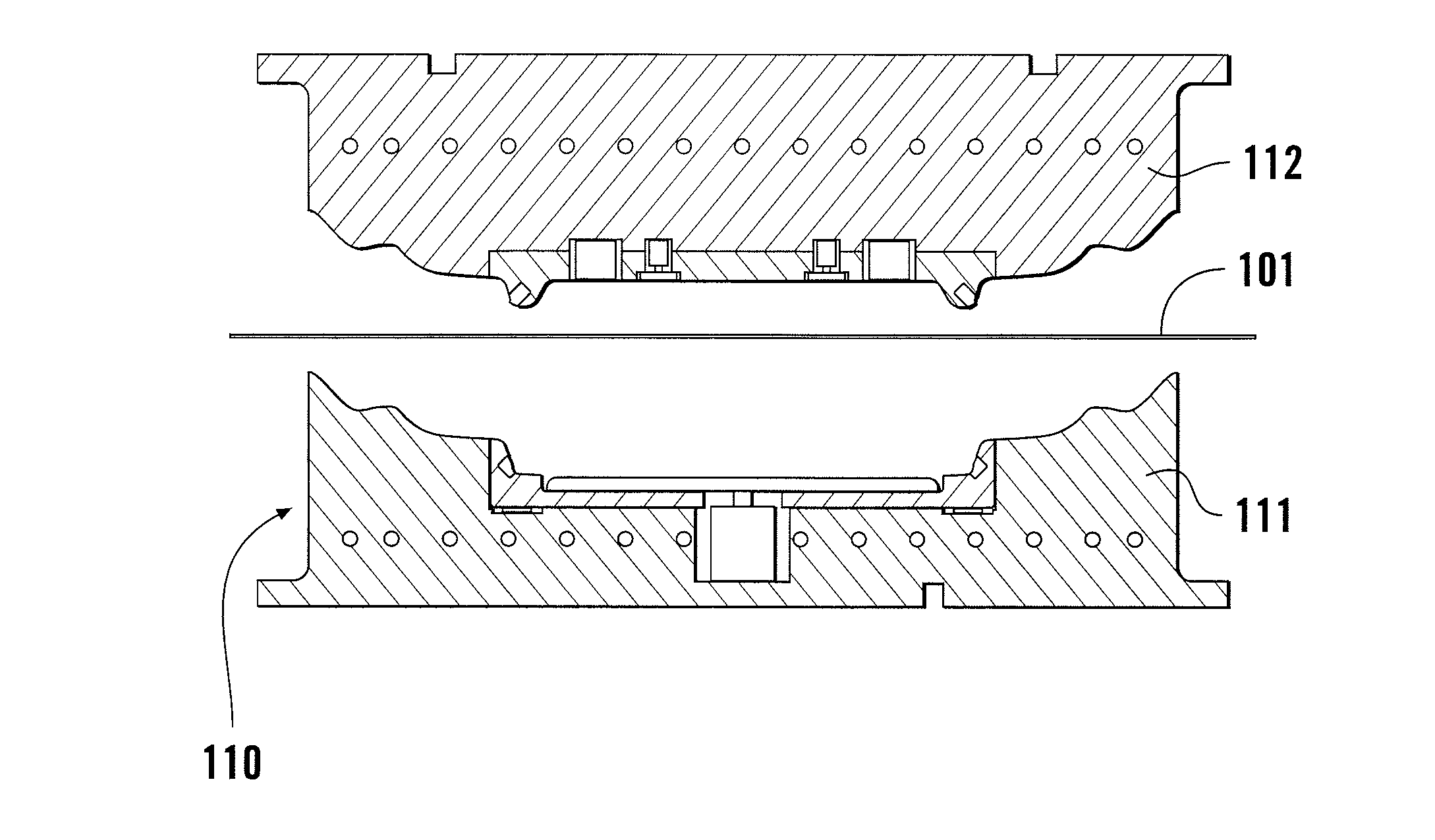
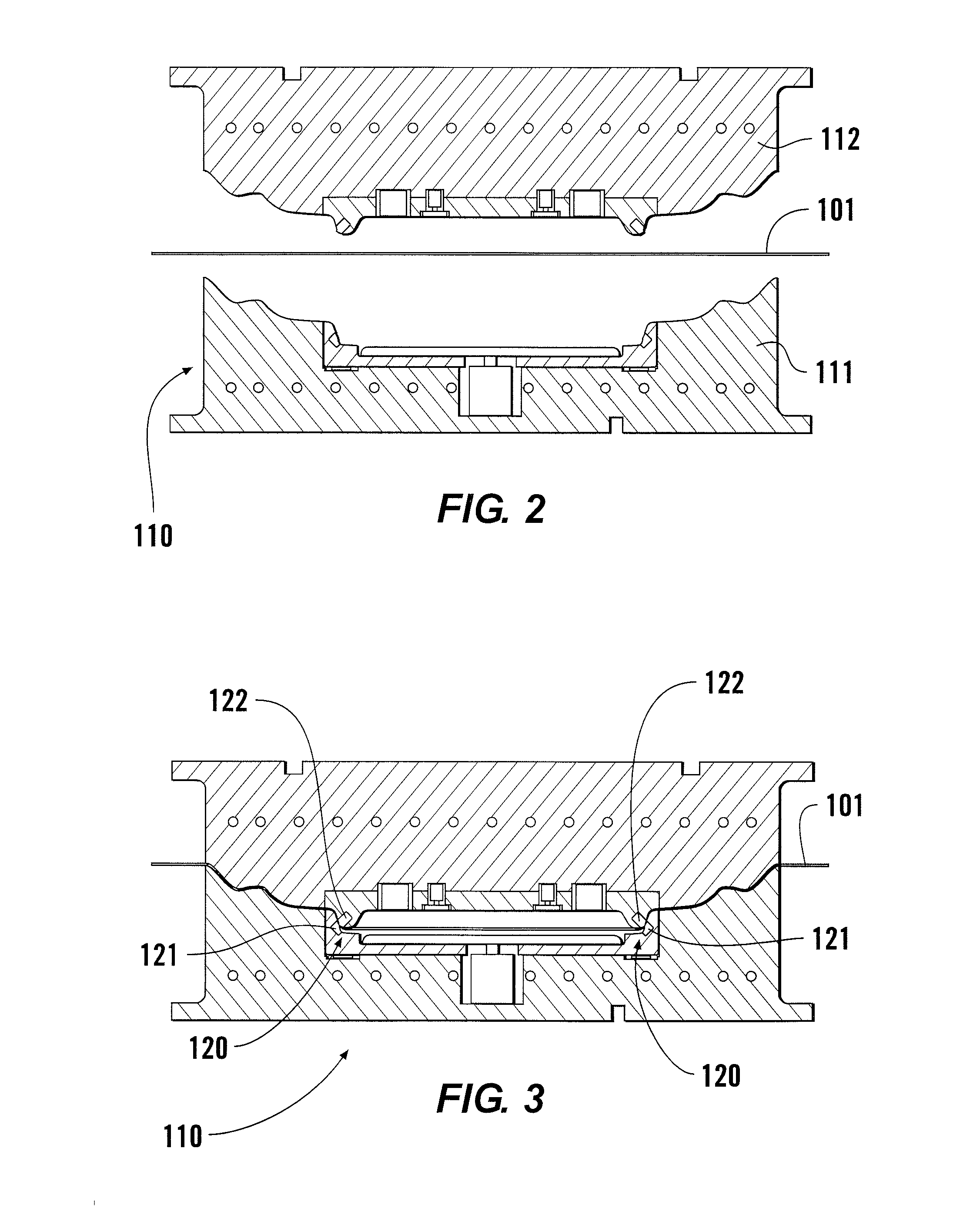
[0037]This invention relates to methods for forming trim panels for vehicle interiors and trim panels made by such processes. More particularly, it relates to methods for forming a clean, attractive edge on trim panels. For purposes of this disclosure, a trim panel is a covering usable to cover any interior surface or component. Such trim panels may be formed by compression molding. Trim panels include, but are not limited to, headliners, door panels, garnishes, instrument panels, seats, consoles, steering wheels, and / or components of such elements. Although the disclosed method is illustrated as applied to only a few types of trim panels, the methods may be adapted to the manufacture of any known or later-developed trim panel.

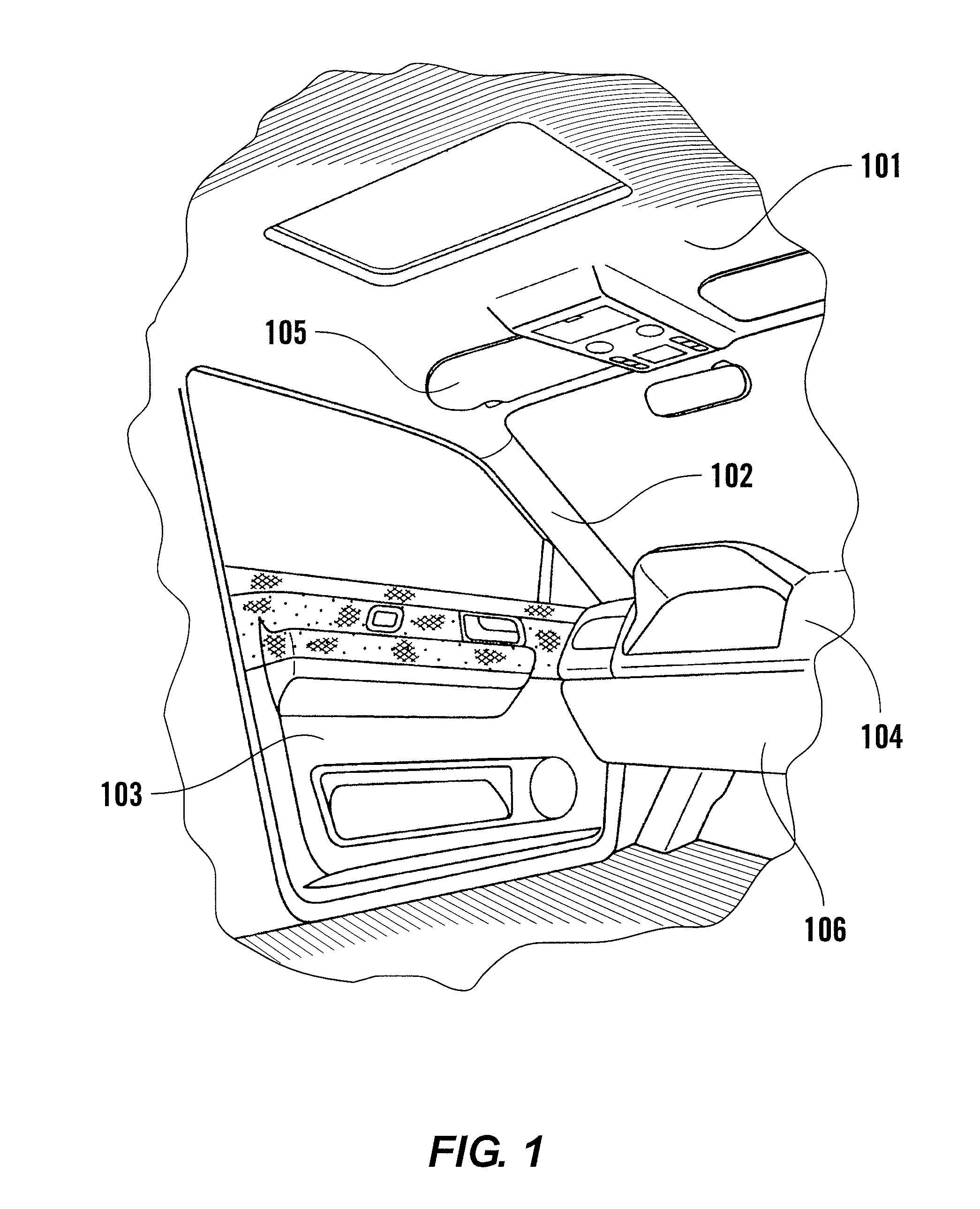
[0038]FIG. 1 shows a vehicle interior with various interior trim pieces or panels including a headliner 101, a garnish 102, a door panel 103, seating components (not shown), a steering wheel (not shown), an instrument panel 104, a sun visor 105, and / or a floor...


PUM

PropertyMeasurementUnit
hardnessaaaaaaaaaa
hardnessesaaaaaaaaaa
widthaaaaaaaaaa

Abstract

A trim panel for a vehicle is formed with a pinch-sealed edge by compression molding. The mold is designed with one or more cutting surfaces that compress or pinch the trim panel material to the point of severing the trim panel to form a tightly compressed and cut edge.

Description

[0001]This application claims priority to U.S. Provisional Application 60 / 996,587 filed Nov. 26, 2007, which is incorporated herein by reference in its entirety.[0002]The following background is provided simply as an aid in understanding the disclosed device and is not admitted to describe or constitute prior art.BACKGROUND[0003]1. Field of the Invention[0004]The present disclosure relates generally to methods and apparatus for forming motor vehicle trim panels such as, for example, garnishes, headliners, and door panels.[0005]2. Related Art[0006]Trim panels are used in occupant compartments of motor vehicles. For example, a vehicle body may include a quarter panel with an inner panel and an outer panel attached to one another and attached to a vehicle structure in some manner. The quarter panel may include a decorative trim panel mounted to the inner panel. The edges of trim panels are generally formed and / or cut in a manner that leaves all of their component parts visible, which p...

Claims


Application Information

Patent Timeline
Patent Type & Authority Applications(United States)
IPC IPC(8): B60R13/02B29C43/02B29C43/40
CPCB29C51/04B29C51/082B29C51/145B29C51/32B29C51/44B60R13/02B29C2793/00B29C2793/0009B29L2031/3011B29L2031/3014B29C67/0044
Inventor SAPAK, BENNELLIS, TODD D.
Owner YANFENG CZECHIA AUTOMOTIVE INTERIOR SYST SRO
Learn More