Power feeding system, power feeder, power-receiving equipment, and positioning control method
a technology of power feeding system and power feeder, which is applied in the direction of transformers, inductances, transportation and packaging, etc., can solve the problems of difficult to ensure high versatility and universality, and the constitution described in the patent document 1 is thought to be quite unfavorable in practice, so as to achieve high universality and versatility.
- Summary
- Abstract
- Description
- Claims
- Application Information
AI Technical Summary
Benefits of technology
Problems solved by technology
Method used
Image

Examples
first embodiment
[2-1 Structure of the Primary Coil Moving Mechanism]
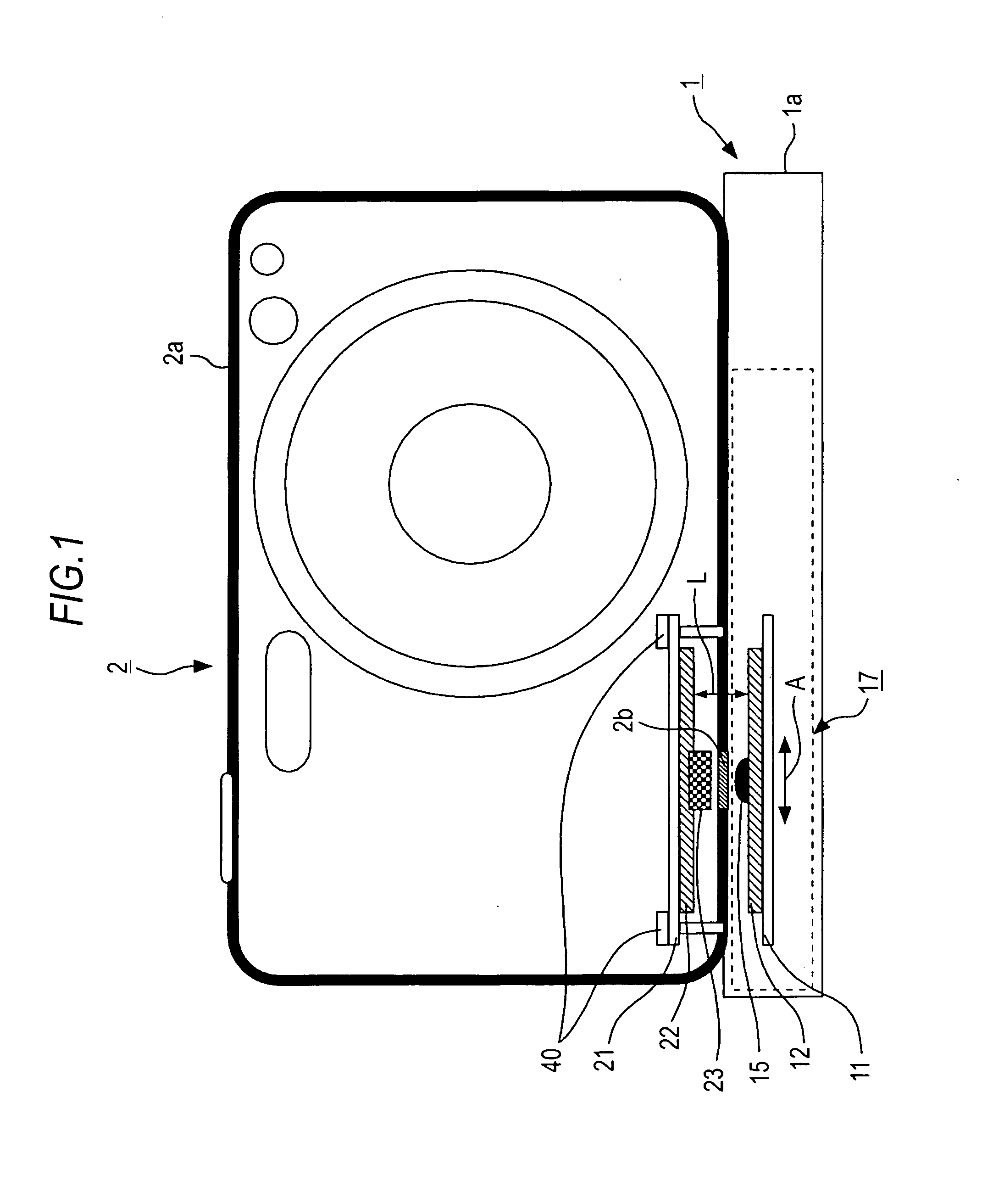
[0078]Next, a first embodiment will be described below.
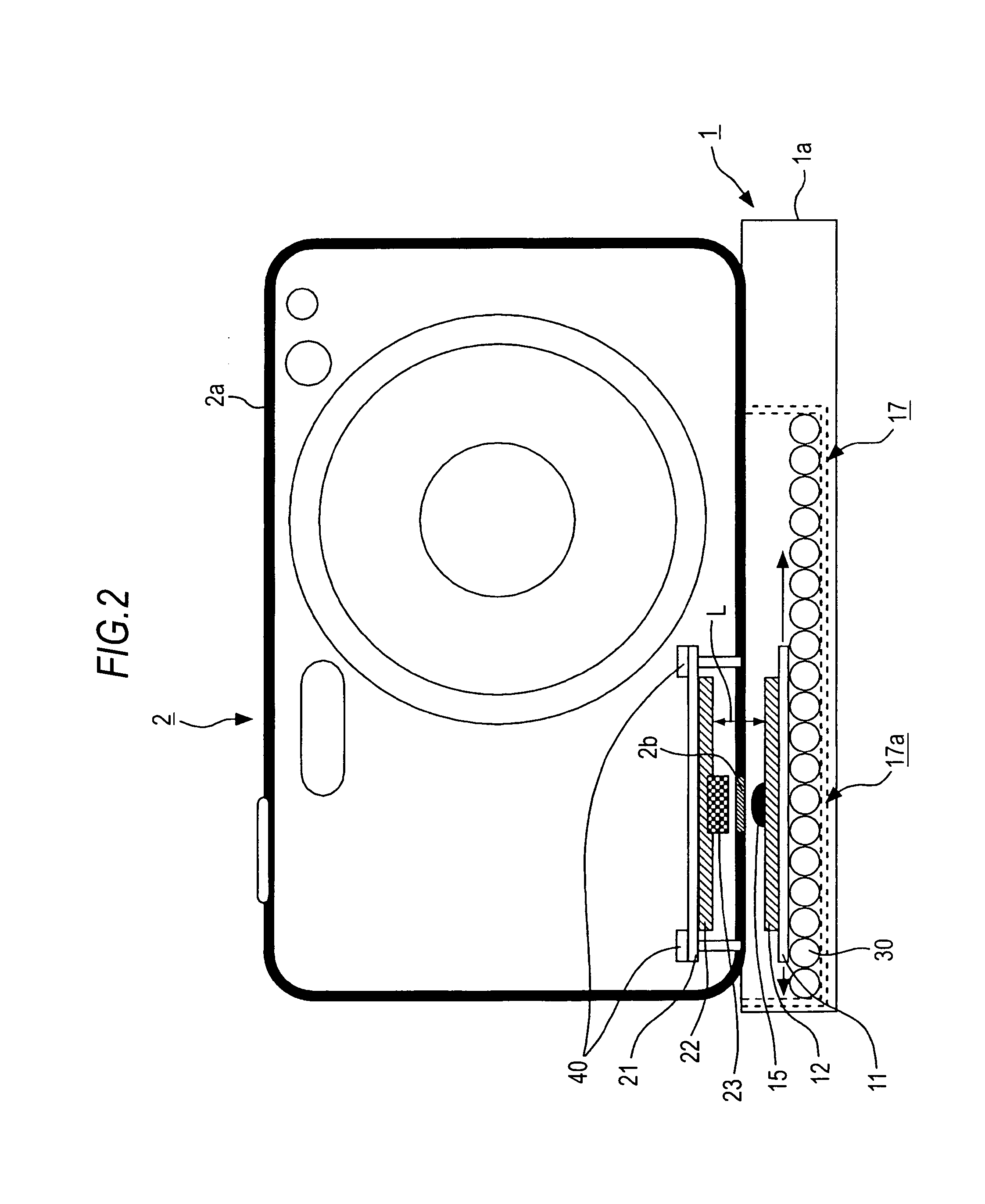
[0079]FIG. 2 shows the charger 1 and equipment to be charged 2 in accordance with the first embodiment. In the first embodiment, the primary coil moving mechanism 17 has a structure that will be concretely described below.
[0080]In the primary coil moving mechanism 17 shown in FIG. 2, a movable member bearing region is structured as a spherical-pieces layer 17a.
[0081]The spherical-pieces layer 17a is formed by, for example, juxtaposing numerous spherical pieces 30, which have a predetermined diameter, in planar directions.
[0082]The substrate 11 to which the primary coil 12 is attached is placed on the spherical-pieces layer 17a. At this time, a distance L that is long enough to ensure necessary and sufficient magnetic coupling is preserved between the primary coil 12 and the secondary coil 22 incorporated in the equipment to be charged 2.
[0083]For forming the spherical-pieces l...
second embodiment
[3-1 Structure of a Primary Coil Moving Mechanism]
[0160]FIG. 5 shows the charger 1 and equipment to be charged 2 included in a non-contact charging system in accordance with the second embodiment. In the drawing, the same reference numerals are assigned to components identical to those shown in FIG. 1 and FIG. 2. An iterative description will be omitted.
[0161]In the second embodiment, the primary coil moving mechanism 17 has a structure described below. Specifically, as illustrated, the primary coil moving mechanism 17 has the structure that an electromagnet 17b is disposed as a movable member bearing region below the substrate 11 to which the primary coil 12 is attached.
[0162]In order to make the primary coil 12 movable using the primary coil moving mechanism 17, the primary coil 12 is driven with a direct current so that the primary coil 12 induces magnetic force, and a current is conducted to the electromagnet 17b so that the electromagnet 17b induces magnetic force. At this time...
third embodiment
[0186][4-1 System configuration]
[0187]FIG. 8 shows an example of a system configuration for the charger 1 and equipment to be charged 2 in accordance with a third embodiment.
[0188]In the drawing, the same reference numerals are assigned to components identical to those shown in FIG. 3 and FIG. 6. An iterative description will be omitted.
[0189]In the system configuration of the third embodiment, the primary coil moving mechanism 17 has the structure that includes the spherical-pieces layer 17a and that is employed in the first embodiment.
[0190]However, the configuration of the third embodiment can be applied to a system in which the primary coil moving mechanism 17 includes the electromagnet 17b similarly to that employed in the second embodiment. In this case, the primary-side control unit 13 of the charger 1 drives the electromagnet 17b.
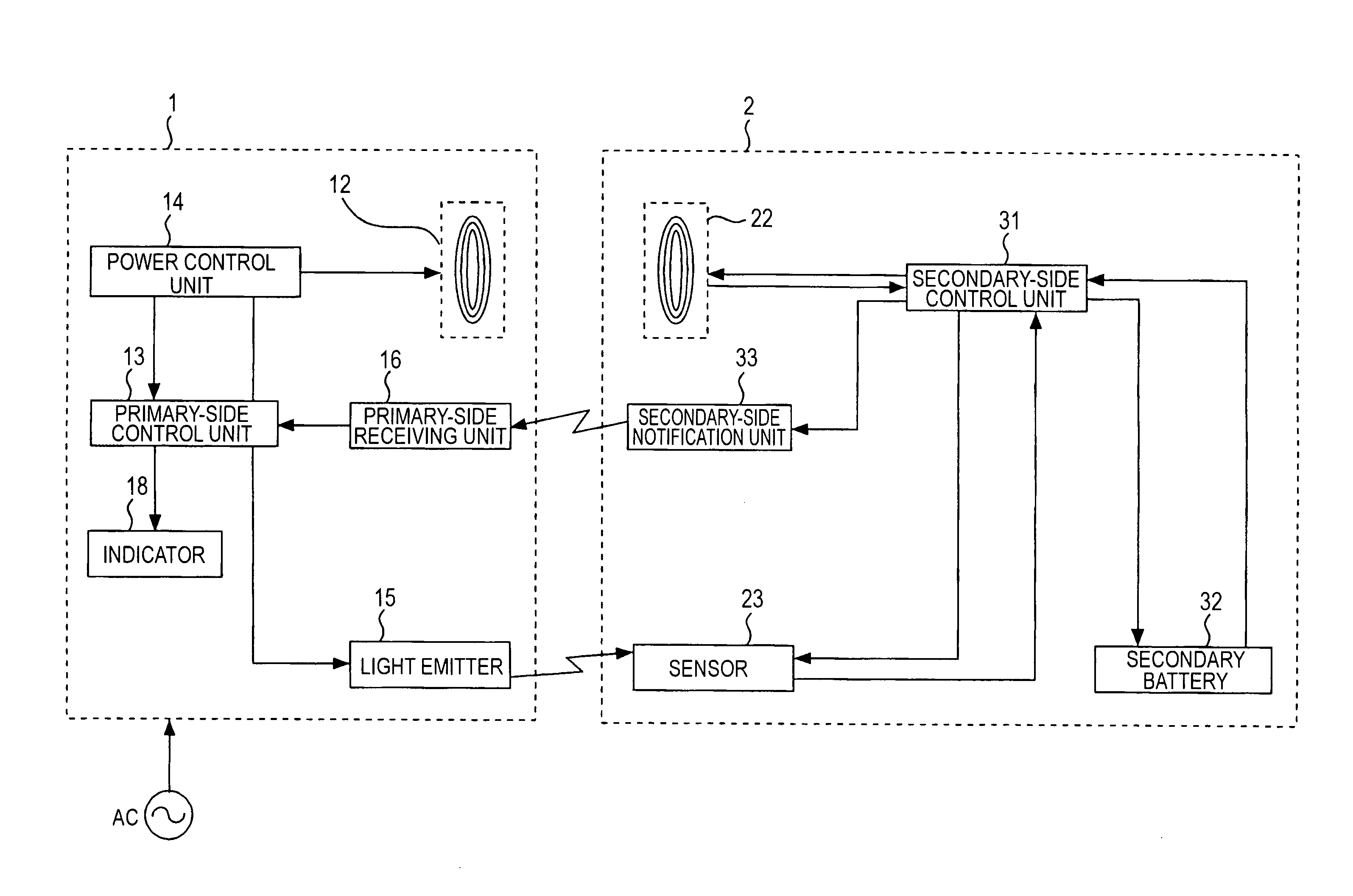
[0191]For example, in the aforesaid first and second embodiments, as shown in FIG. 1, FIG. 2, and FIG. 5, the charger 1 includes the light emitter...
PUM
 Abstract
Description
Claims
Application Information
 - Generate Ideas
- Intellectual Property
- Life Sciences
- Materials
- Tech Scout
- Unparalleled Data Quality
- Higher Quality Content
- 60% Fewer Hallucinations
Browse by: Latest US Patents, China's latest patents, Technical Efficacy Thesaurus, Application Domain, Technology Topic, Popular Technical Reports.
© 2025 PatSnap. All rights reserved.Legal|Privacy policy|Modern Slavery Act Transparency Statement|Sitemap|About US| Contact US: help@patsnap.com