

Electric motor and electric vehicle
- Summary
- Abstract
- Description
- Claims
- Application Information
AI Technical Summary
Benefits of technology
Problems solved by technology
Method used
Image

Examples
first embodiment
Configuration of Electric Motor
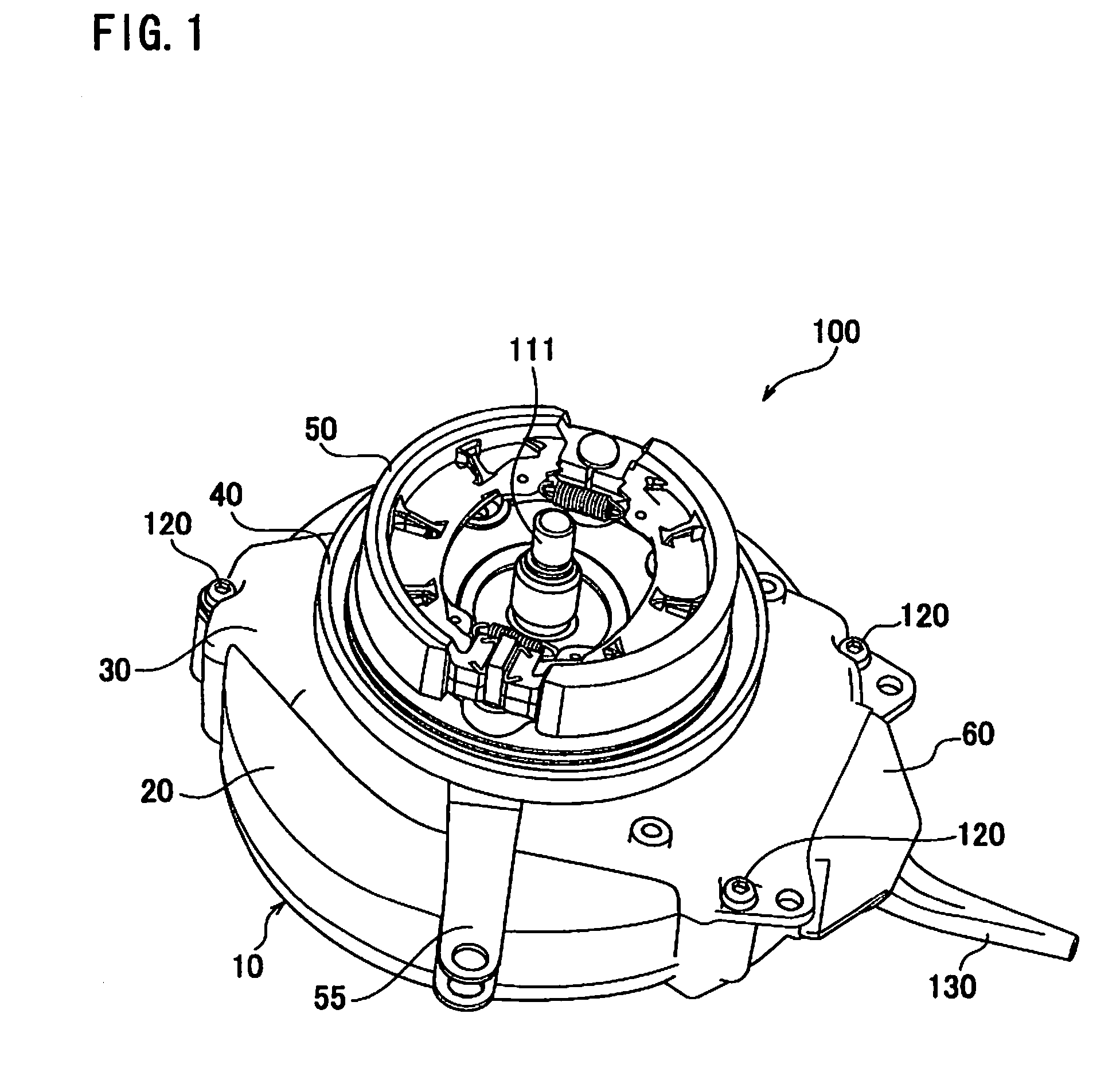
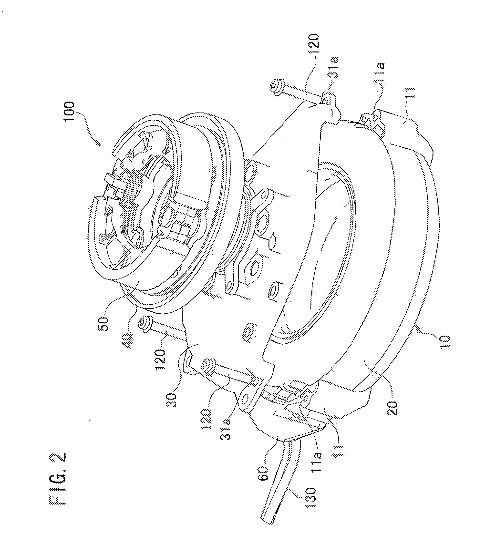
[0048]Hereinafter, an electric motor according to a first embodiment will be described with reference to the drawings. FIG. 1 is a perspective view showing an electric motor 100 according to the first embodiment. FIG. 2 is an exploded perspective view showing the electric motor 100 according to the first embodiment. FIG. 3 is an exploded view showing the electric motor 100 according to the first embodiment.
[0049]As shown in FIGS. 1 to 3, the electric motor 100 includes a casing member 10, a resin 20, a cushion member 30, a holding member 40, a brake mechanism 50 and a terminal cover 60.
[0050]The casing member 10 holds a stator core 70 (not shown, refer to FIG. 5) to be described later. The casing member 10 is formed of a member having a predetermined rigidity, such as a metal member. The casing member 10 has guide ribs 11 having bolt holes 11a which have spiral grooves. The casing member 10 has an opening 13a (not shown, refer to FIG. 4), as will be de...
modified example 1
[0124]Hereinafter, Modified Example 1 of the first embodiment will be described. In the following description, the differences from the first embodiment will mainly be described.
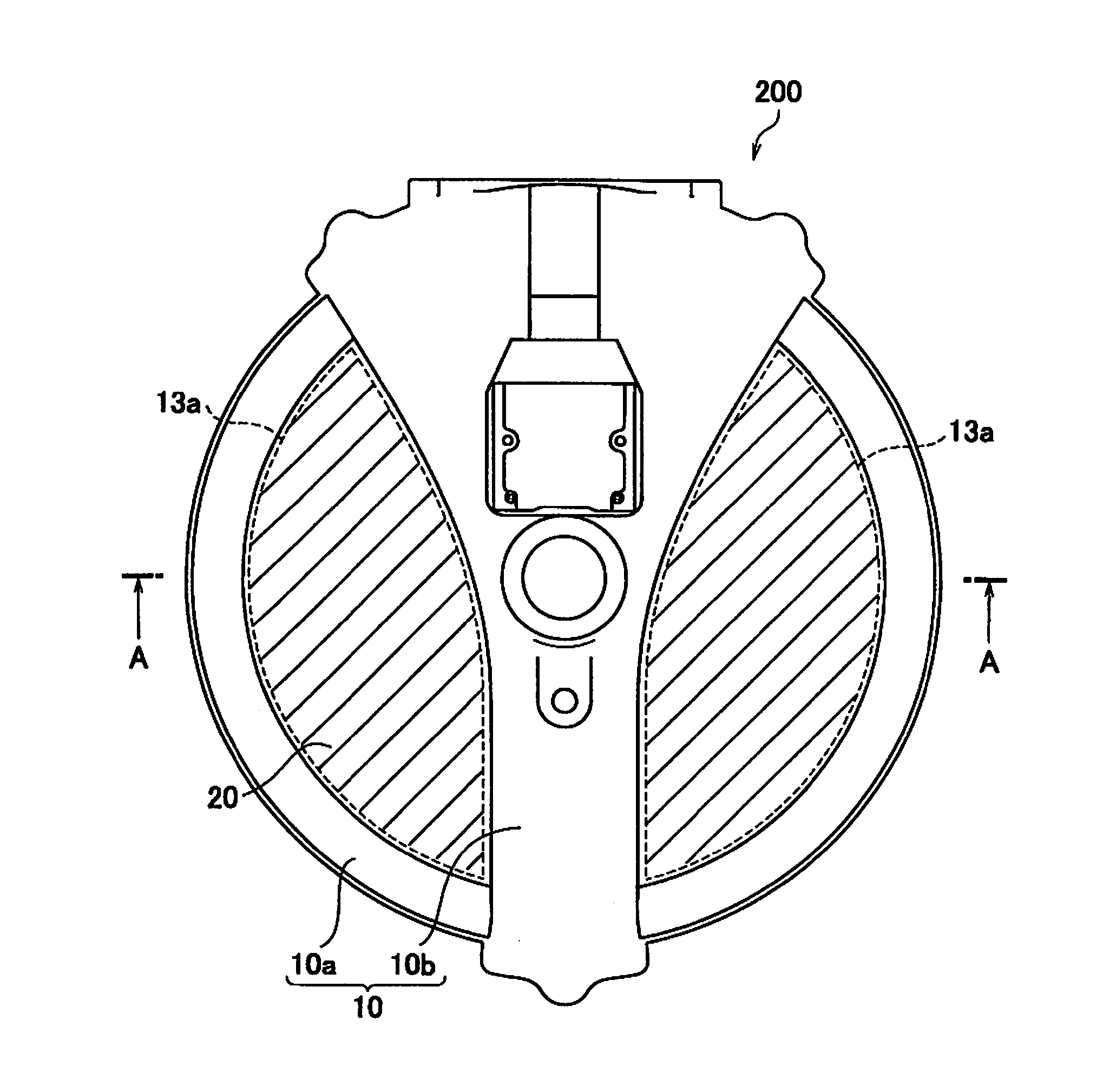
[0125]Although details for the first embodiment are not described, tip portions 72a of stator teeth 72 form a cavity with a polygonal columnar shape in Modified Example 1. In a lower unit 200, parts of the tip portions 72a of the stator teeth 72 and a resin 20 form a cylindrical cavity for housing a rotor capable of rotating about an axle 111.
[0126]FIGS. 17 and 18 are views for describing a method of forming the cavity for housing the rotor (not shown) in the lower unit 200 according to Modified Example 1.
[0127]As shown in FIG. 17, the cavity formed of the tip portions 72a of the stator teeth 72 has a polygonal cross-section. At the time of filling the resin 20, an axis center mold 420 is disposed in the cavity formed of the tip portions 72a of the stator teeth 72.
[0128]The axis center mold 420 has a cylindr...
second embodiment
[0136]Hereinafter, a second embodiment will be described with reference to the drawings. Specifically, in the second embodiment, amounting structure of a casing member 10, a cushion member 30 and a holding member 40 will be described.
[0137]FIG. 19 is an exploded perspective view showing an electric motor 100 according to the second embodiment. FIG. 20 is a cross-sectional view showing the electric motor 100 according to the second embodiment. Note that, in FIG. 19, a rear wheel 520 for housing the brake mechanism 50 is shown.
[0138]As shown in FIG. 19, a center axis of the rear wheel 520 is provided coaxially with rotation axes S of the axle 111, and a gear shaft 112 disposed inside a resin 20. Moreover, the center axis of each of the resin 20, a holding member 40 and the brake mechanism 50 is set coaxially with the rotation axes S.
[0139]The cushion member 30 is fixed to the resin 20 in a way that bolts 120 are screwed into bolt holes 11a of guide ribs 11 through the bolt holes 31a o...
PUM
 Abstract
Description
Claims
Application Information