Matched RF output transition for a high-power microwave electron tube

a high-power microwave electron tube and output transition technology, which is applied in the direction of transit-tube coupling devices, traveling-wave tubes, electric discharge tubes, etc., can solve the problems of limiting the behaviour of the arc over time, reducing the efficiency of sfsub>6 /sub>gas for pressurization, and increasing the field locally. , to achieve the effect of sufficient breakdown strength and reducing the breakdown level

Active Publication Date: 2010-11-25
THALES SA
View PDF5 Cites 1 Cited by
  • Summary
  • Abstract
  • Description
  • Claims
  • Application Information

AI Technical Summary

Benefits of technology

[0045]The main transition objective according to the invention is to make it possible to use, in the RF power output circuit of a tube, a pressurization gas having no greenhouse effect and harmless to maintenance personnel, suc...

Problems solved by technology

The output of the klystron includes arc detectors, but as rapid as they are these detectors can only be triggered at the moment when the breakdown occurs, which nevertheless limits the behaviour of the arc over time.
One weakness of this type of transition of the prior art shown in FIG. 2 is that of having a region with an electric field locally increased because of the geometry of this zone, the electric field being able to locally exceed the breakdown threshold.
As a result, the transition becomes t...

Method used


Image

  • Matched RF output transition for a high-power  microwave electron tube
  • Matched RF output transition for a high-power  microwave electron tube
  • Matched RF output transition for a high-power  microwave electron tube

Examples


Embodiment Construction

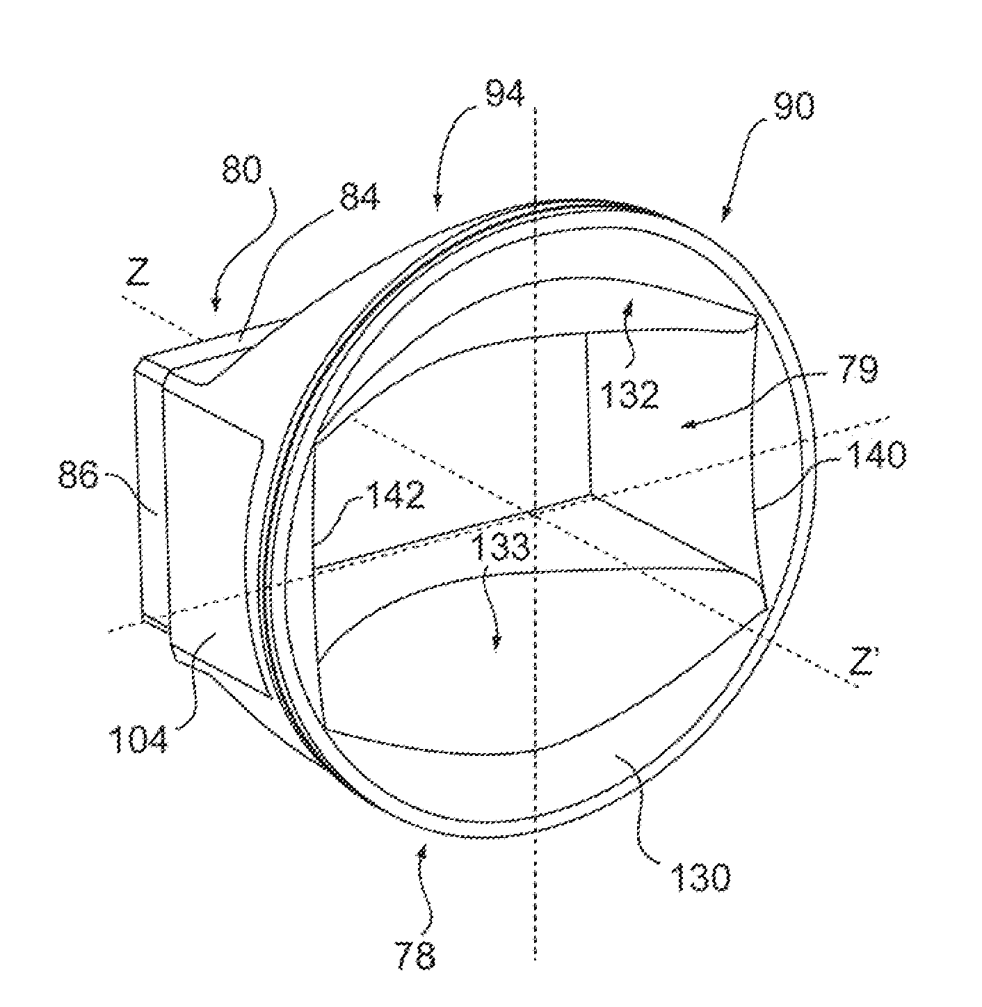
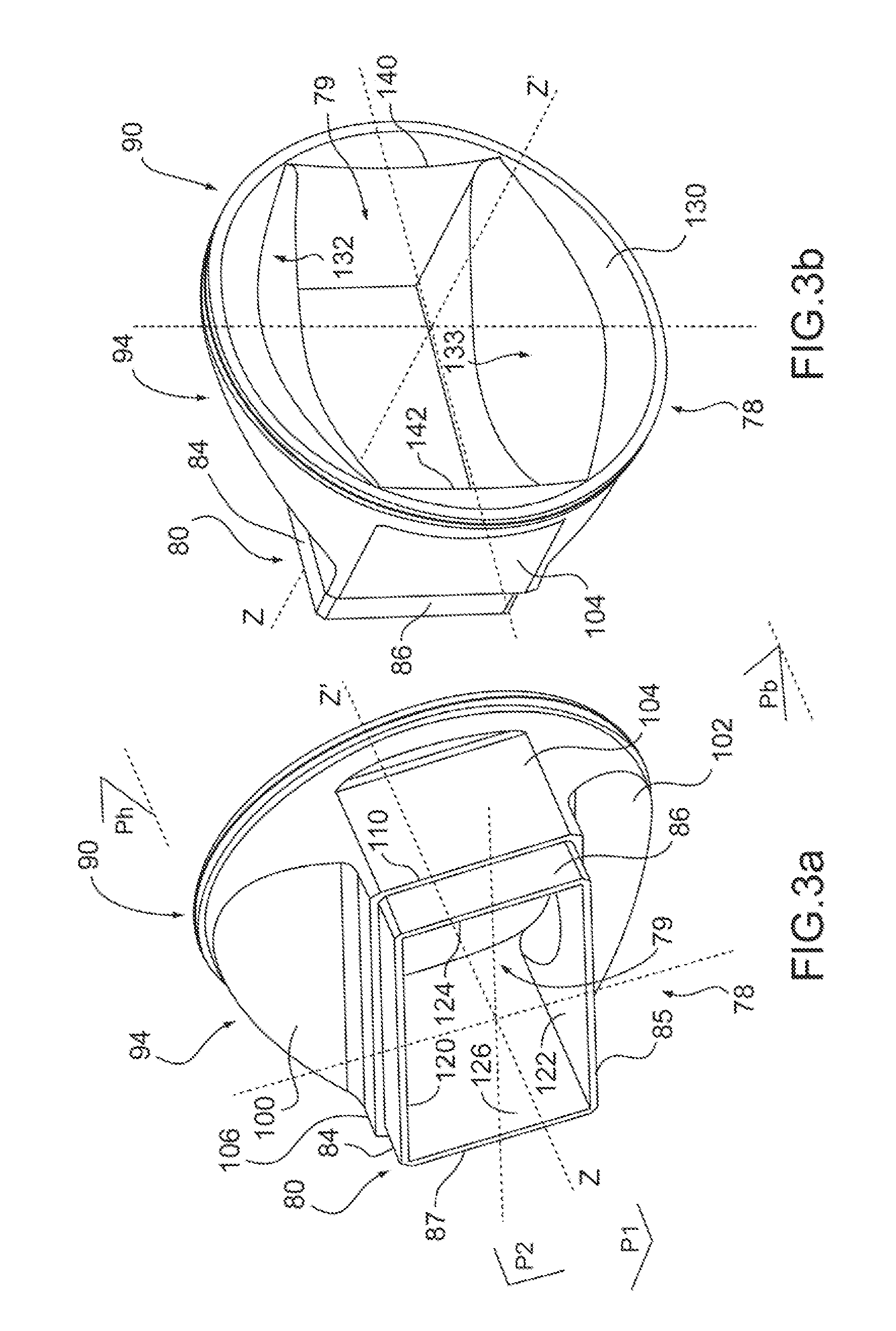
[0056]FIGS. 3a and 3b show two line diagrams in perspective of the body of a transition according to the invention.

[0057]The transition according to the invention comprises a body 78 of tubular shape, along a longitudinal axis ZZ′, having two ends and a passage 79 between the two ends. One of the ends 80 is in the form of a tube of rectangular cross section, having two parallel long sides 84, 85 and two short sides 86, 87 perpendicular to the long sides, the other end 90 being in the form of a circular tube.

[0058]The end 80 of rectangular cross section is intended to receive a connecting flange (not shown in the figure) for connection to an application waveguide, likewise of rectangular cross section; the circular end 90 of which being intended to be connected to the RF output of the electron tube.

[0059]The body of the transition further includes a central portion 94 between the rectangular tubular end 80 and the circular tubular end 90.

[0060]The body of the transition comprises ext...


PUM


Abstract

The invention relates to a microwave output transition for a high-power electron tube comprising a body (78) of tubular shape, along a longitudinal axis ZZ′, having two ends (80, 90), a passage (79) between the two ends that has internal surfaces for propagating electromagnetic waves, one of the ends (90), in the form of a circular cylindrical tube, comprising a conical internal propagation surface (130) and the other end (80), in the form of a tube of rectangular cross section, having two long sides (84, 85) and two short sides (86, 87) perpendicular to the long sides, the passage having two plane internal propagation surfaces (120, 122) parallel to the long sides (84, 85) and two other plane internal surfaces (124, 126) parallel to the short sides (86, 87).
Each of the plane internal propagation surfaces (120, 122) parallel to the long sides (84, 85) is joined to the conical internal propagation surface (130) via a respective curved connecting surface (132, 133) having bidirectional radii of curvature.

Description

CROSS REFERENCE TO RELATED APPLICATIONS[0001]The present application claims priority to French Patent Application Serial No. 0807393, filed Dec. 23, 2008, which is incorporated by reference in its entirety.FIELD OF THE INVENTION[0002]The present invention relates to a transition between a radiofrequency output of a high-power microwave tube and a waveguide.BACKGROUND OF THE INVENTION[0003]High-power microwave electron tubes, such as klystrons operating in the L-band, i.e. in a frequency band from 1 to 2 GHz, comprise at least one high-power RF output intended to be connected to a waveguide in order to transmit the RF power delivered by the tube to a microwave use circuit.[0004]The output cavity of the klystron is connected to the waveguide via a microwave window transparent to the electromagnetic waves. The microwave window isolates the inside of the tube which is under vacuum from the outside, which is possibly under pressure of a gas. Furthermore, a transition after the microwave ...

Claims


Application Information

Patent Timeline
IPC IPC(8): H01P1/08
CPCH01J23/36H01J23/12
Inventor MARCHESIN, RODOLPHEBARIOU, DAVIDPIQUET, JEAN-LUCAGOGUE, SERGE
Owner THALES SA
Why Eureka
Try Eureka