Superconductive magnet

a superconductive magnet and superconductive technology, applied in the direction of superconducting magnets/coils, magnetic bodies, instruments, etc., can solve the problems of increasing the amount of materials used, weight and the cost of production, cooling, transportation, etc., and achieve the effect of reducing the amount of materials and machining costs

Active Publication Date: 2010-11-25
CANON MEDICAL SYST COPRPORATION
View PDF7 Cites 30 Cited by
  • Summary
  • Abstract
  • Description
  • Claims
  • Application Information

AI Technical Summary

Benefits of technology

[0011]The present invention has been implemented in order to solve the foregoing problems; the objective thereof is to provide a superconductive magnet in which there are reduced the machining costs and the amount of materials for bobbins and supporting members that support coils.
[0014]In a superconductive magnet according to the present invention, the shield bobbin and the bobbin supporting member can be simplified; therefore, the amount of materials for the shield-coil supporting structure and the machining cost can be reduced. Furthermore, the weight of the whole magnet can be reduced; thus, the amount of coolant required for cooling can be reduced. Accordingly, in order to cope with the increase, in the material costs and machining costs of bobbins and supporting structures, which is caused by the increase in the electromagnetic force of a superconductive magnet, the amount of used bobbin materials and supporting members is considerably reduced; therefore, the costs of material procurement, machining, and cooling can be reduced, and the weight saving can also be achieved.

Problems solved by technology

In the conventional technology, by forming the main bobbin 21, the shield bobbin 31, and the shield bobbin supporting member 32 in a more rigid structure, a structure that can withstand electromagnetic force has been realized; however, there has been a problem that, the amount of materials utilized in the bobbins and the supporting structure increases as the electromagnetic force of a superconductive magnet is enlarged lately, and hence the weight and the costs in production, cooling, and transportation increase.

Method used


Image

  • Superconductive magnet
  • Superconductive magnet
  • Superconductive magnet

Examples


embodiment 1

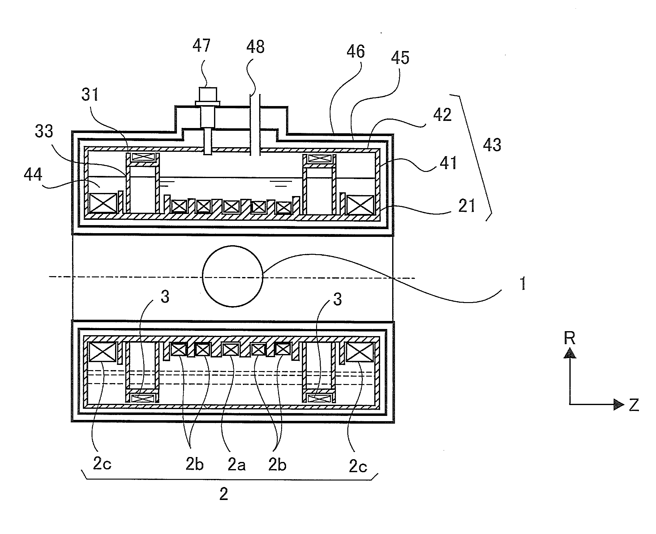
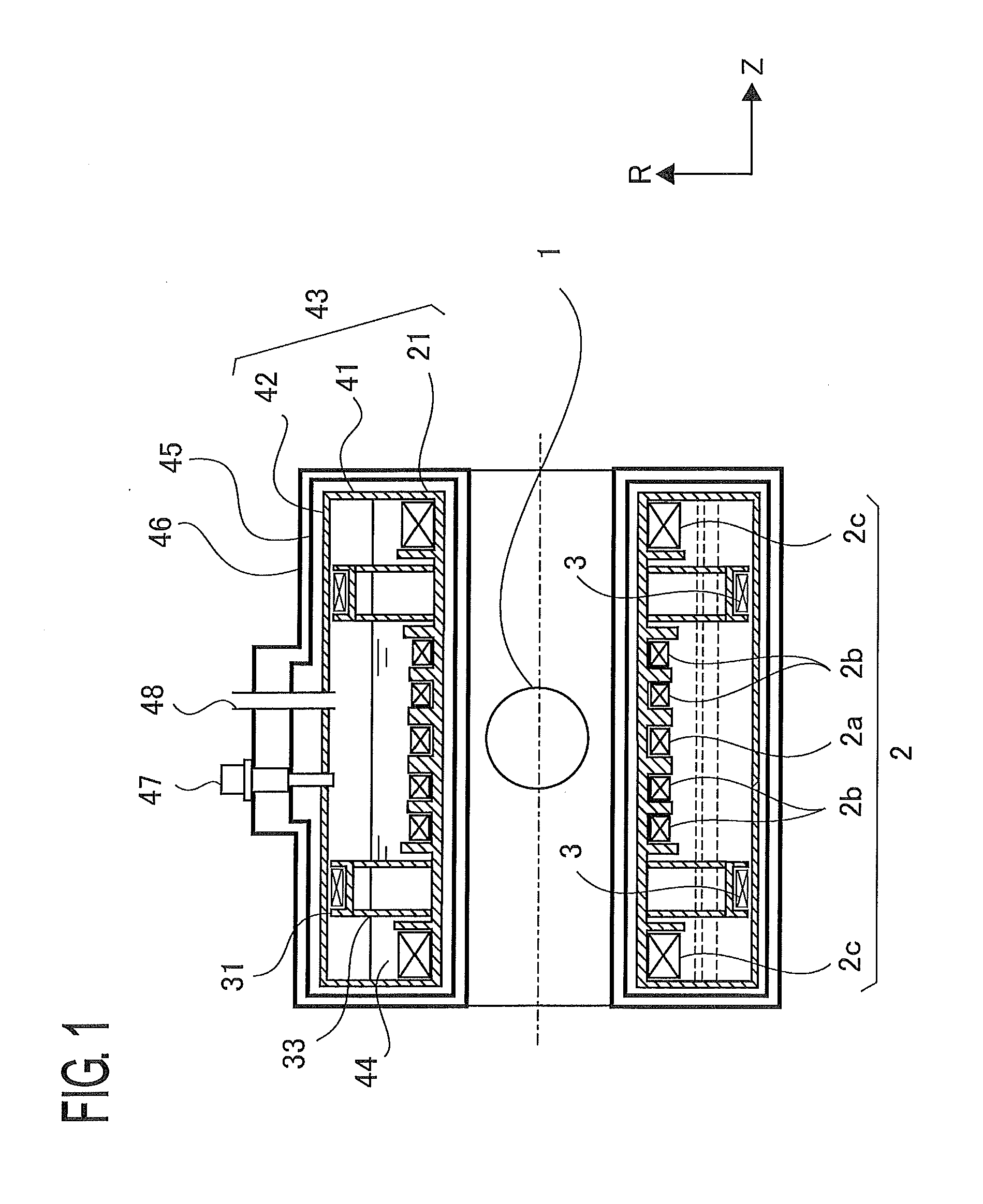
[0029]FIG. 1 is a cross-sectional view, taken along a plane parallel to the Z axis, of a superconductive magnet according to Embodiment 1 of the present invention. In addition, in each of the figures, the same reference marks indicate the same or equivalent constituent elements, and some of explanations therefor will be omitted. In FIG. 1, reference numeral 1 denotes a magnetic-field generation region where a magnetic field is produced; reference numeral 2 denotes a main coil for generating a desired magnetic field in the magnetic-field generation region 1; reference numeral 3 denotes a shield coil for cancelling a magnetic field that leaks outward. The shield coil 3 is disposed in such a way as to be coaxial with the Z axis of the main coil 2 and more distal than the main coil 2 from the Z axis (the radial distance between the Z axis and the center of the shield coil 3 is larger than the radial distance between the Z axis and the center of the main coil 2). The main coil 2 and the ...

embodiment 2

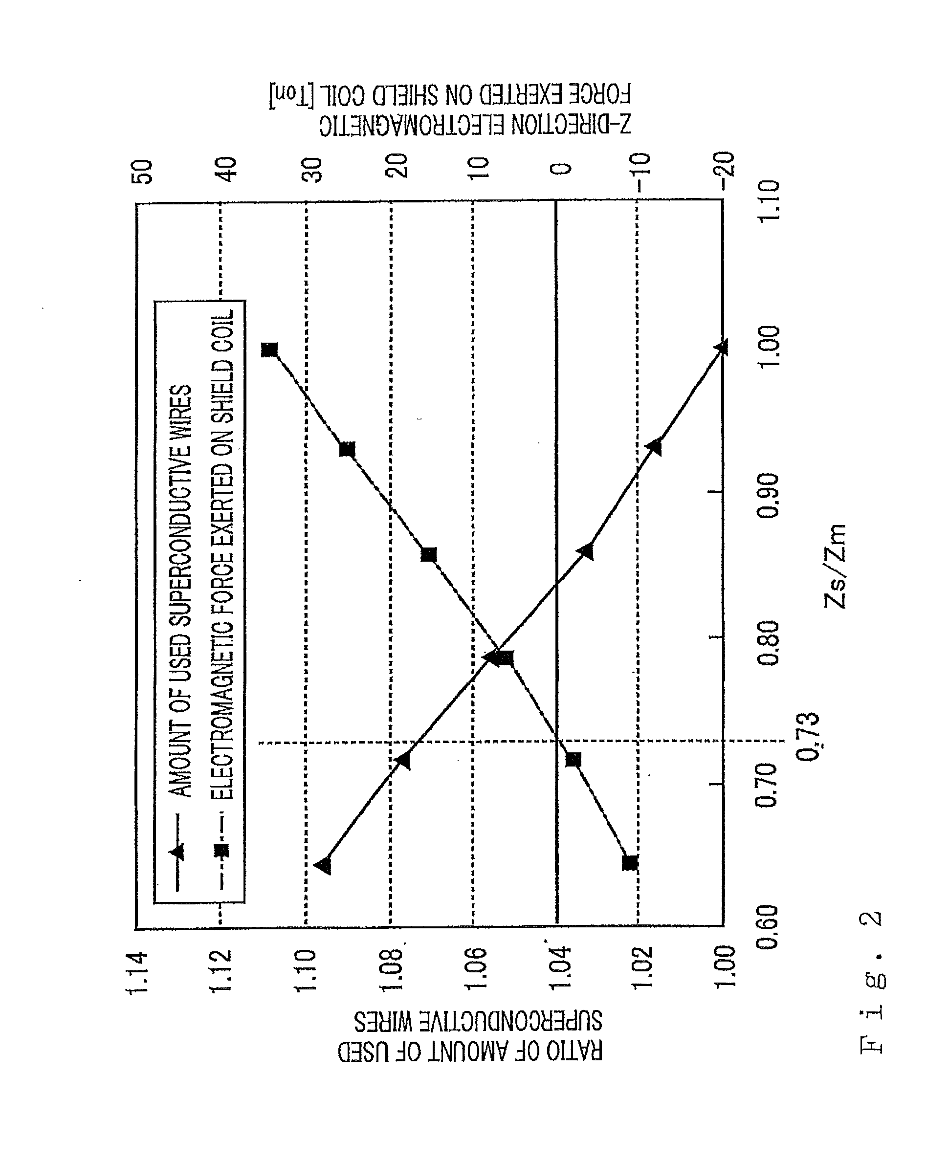
[0041]FIG. 4 is a cross-sectional view, taken along a plane parallel to the Z axis, of a superconductive magnet according to Embodiment 2. FIG. 5 is a cross-sectional view, taken along a plane perpendicular to the Z axis, of the superconductive magnet in FIG. 4. The superconductive magnet according to Embodiment 2 is similar to the superconductive magnet according to Embodiment 1 in that there are included a main coil 2, a main bobbin 21, shield coils 3, shield bobbins 31, helium tank flanges 41, a helium tank outer cylinder 42, a thermal shield 45, a vacuum tank 46, a refrigerator 47, and a service port 48. The arrangement of the shield coil 3 is similar to the superconductive magnet according to Embodiment 1 in that Zs / Zm is made to be approximately 0.73, in order to arrange the shield coil 3 at a position where the Z-direction electromagnetic force exerted on the shield coil 3 is minimized while the increase in the amount of used superconductive wires is suppressed.

[0042]A shield...

embodiment 3

[0044]FIG. 6 is a cross-sectional view, taken along a plane parallel to the Z axis, of a superconductive magnet according to Embodiment 3. FIG. 7 is a cross-sectional view, taken along a plane perpendicular to the Z axis, of the superconductive magnet in FIG. 6. The superconductive magnet according to Embodiment 3 is similar to the superconductive magnet according to Embodiment 1 in that there are included a main coil 2, a main bobbin 21, shield coils 3, shield bobbins 31, helium tank flanges 41, a helium tank outer cylinder 42, a thermal shield 45, a vacuum tank 46, a refrigerator 47, and a service port 48. The arrangement of the shield coil 3 is similar to the superconductive magnet according to Embodiment 1 in that Zs / Zm is made to be approximately 0.73, in order to arrange the shield coil 3 at a position where the Z-direction electromagnetic force exerted on the shield coil 3 is minimized while the increase in the amount of used superconductive wires is suppressed.

[0045]In Embod...


PUM

PropertyMeasurementUnit
diameteraaaaaaaaaa
magnetic fieldaaaaaaaaaa

Abstract

There is obtained a superconductive magnet in which there are reduced the machining costs and the amount of materials for bobbins and supporting members that support coils. In a superconductive magnet provided with a first group of coils serving as main coils for generating a magnetic field and a second group of coils serving as shield coils that are arranged coaxially with the first group of coils and generate a magnetic field whose direction is opposite the direction of a magnetic field generated by the first group of coils so that a magnetic field that leaks outside is cancelled, the second group of coils are arranged at axis-direction positions where axis-direction electromagnetic force generated by the first group of coils and exerted on the second group of coils and axis-direction electromagnetic force generated by the second group of coils balance with each other and cancel out each other.

Description

BACKGROUND OF THE INVENTION[0001]1. Field of the Invention[0002]The present invention relates to a superconductive magnet utilized mainly in a magnetic resonance imaging (MRI) system, a nuclear magnetic resonance (NMR) analysis system, a monocrystal pulling system, and the like.[0003]2. Description of the Related Art[0004]In an MRI system, an NMR analysis system, and a monocrystal pulling system, because measurement or production of a monocrystal requires a high magnetic field, a superconductive magnet is utilized.[0005]FIG. 12 is a cross-sectional perspective view illustrating the structure for a conventional superconductive magnet. FIG. 13 is a cross-sectional plan view of the conventional superconductive magnet in FIG. 12. A superconductive magnet is required to generate a high magnetic field in a desired region (referred to as a magnetic-field generation region 1, hereinafter). Taking a MRI superconductive magnet as an example, it is required to generate a high magnetic field of...

Claims


Application Information

Patent Timeline
Patent Type & Authority Applications(United States)
IPC IPC(8): H01F6/06
CPCG01R33/3815Y10T29/49014H01F6/06
Inventor TAMURA, HAJIME
Owner CANON MEDICAL SYST COPRPORATION
Why Eureka
Try Eureka