Information processing apparatus and calibration processing method

a technology of information processing and calibration processing, which is applied in the field of camera calibration technique, can solve the problems of user unnatural feeling and adversely affecting the body of the user

Active Publication Date: 2010-11-25
CANON KK
View PDF28 Cites 34 Cited by
  • Summary
  • Abstract
  • Description
  • Claims
  • Application Information

AI Technical Summary

Benefits of technology

[0009]The present invention has been made in consideration of the aforementioned problems, and one preferred embodiment of the present invention provides an information processing apparatus and calibration processing method which can prevent display of a VR space from adversely affecting the body of a viewer when the camera intrinsic parameters and the relative position and orientation between cameras have changed.

Problems solved by technology

However, the relative position and orientation between the two cameras may often fail to be constant due to errors of the sensors, thus making the user feel unnatural.
However, the camera intrinsic parameters and the relative position and orientation between the two cameras often change when the HMD is inadvertently dropped or due to arbitrary external factors.
When the user continues a job while wearing the HMD in such state, a normal stereoscopic viewing disturbance may adversely affect the body of the user.

Method used


Image

  • Information processing apparatus and calibration processing method
  • Information processing apparatus and calibration processing method
  • Information processing apparatus and calibration processing method

Examples


first embodiment

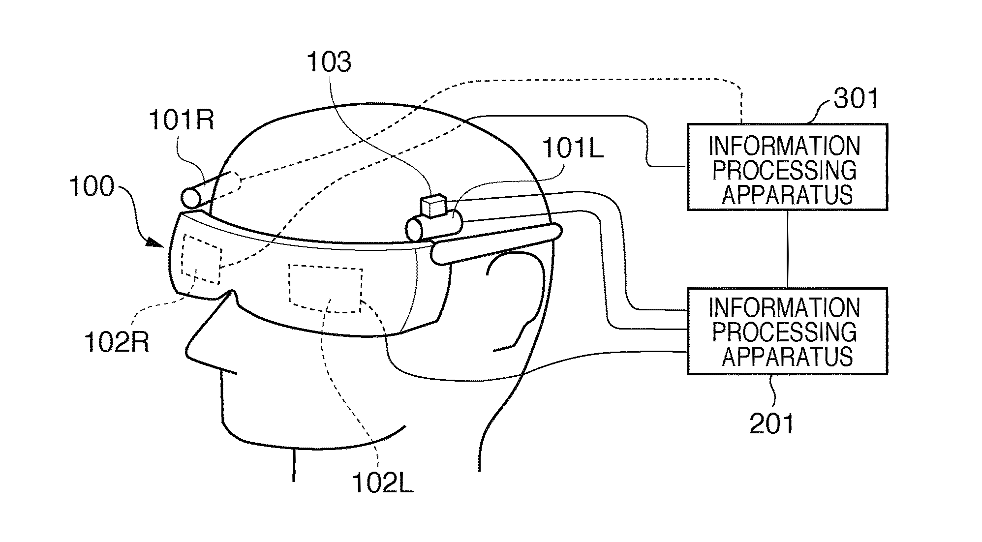
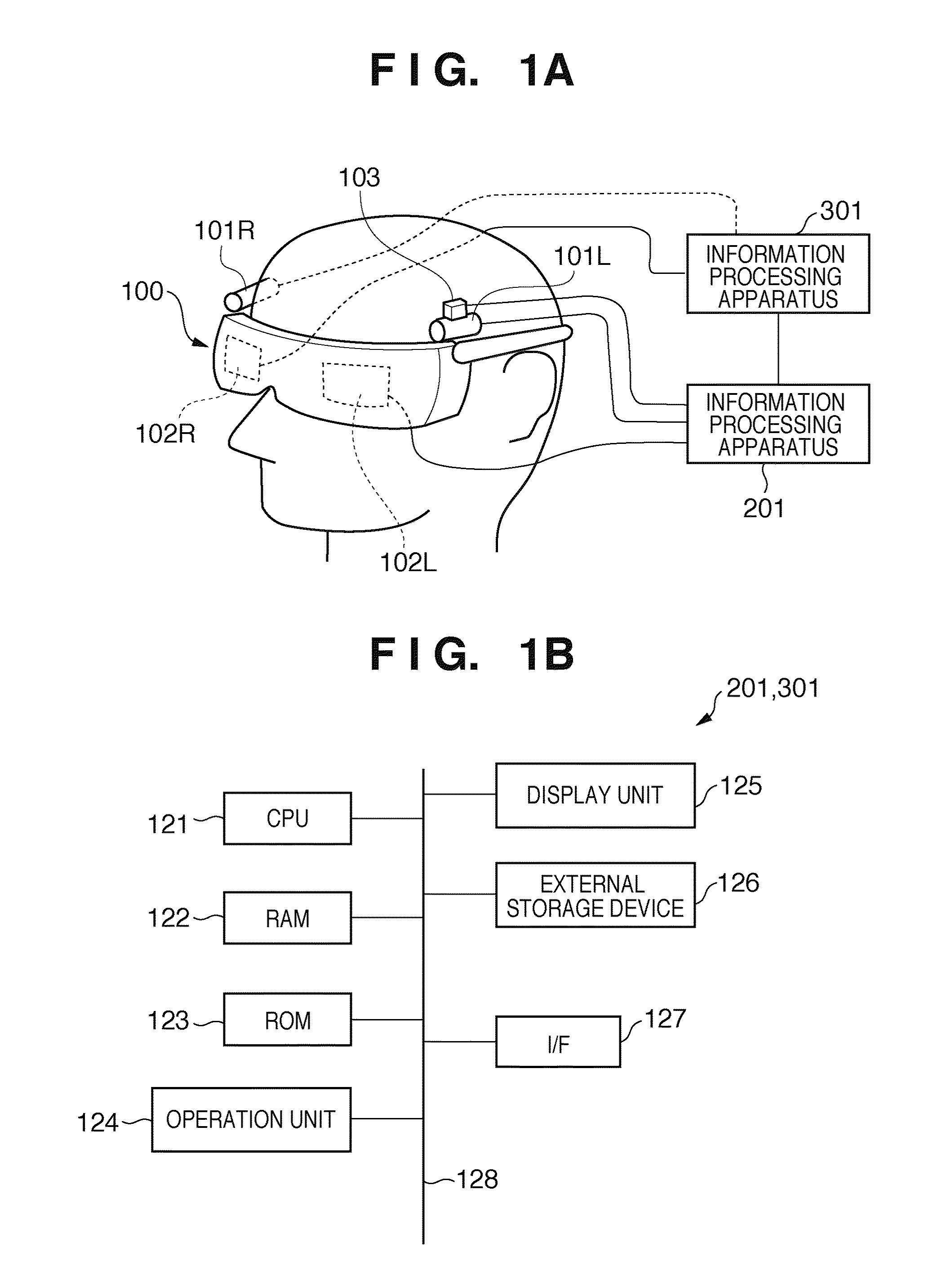
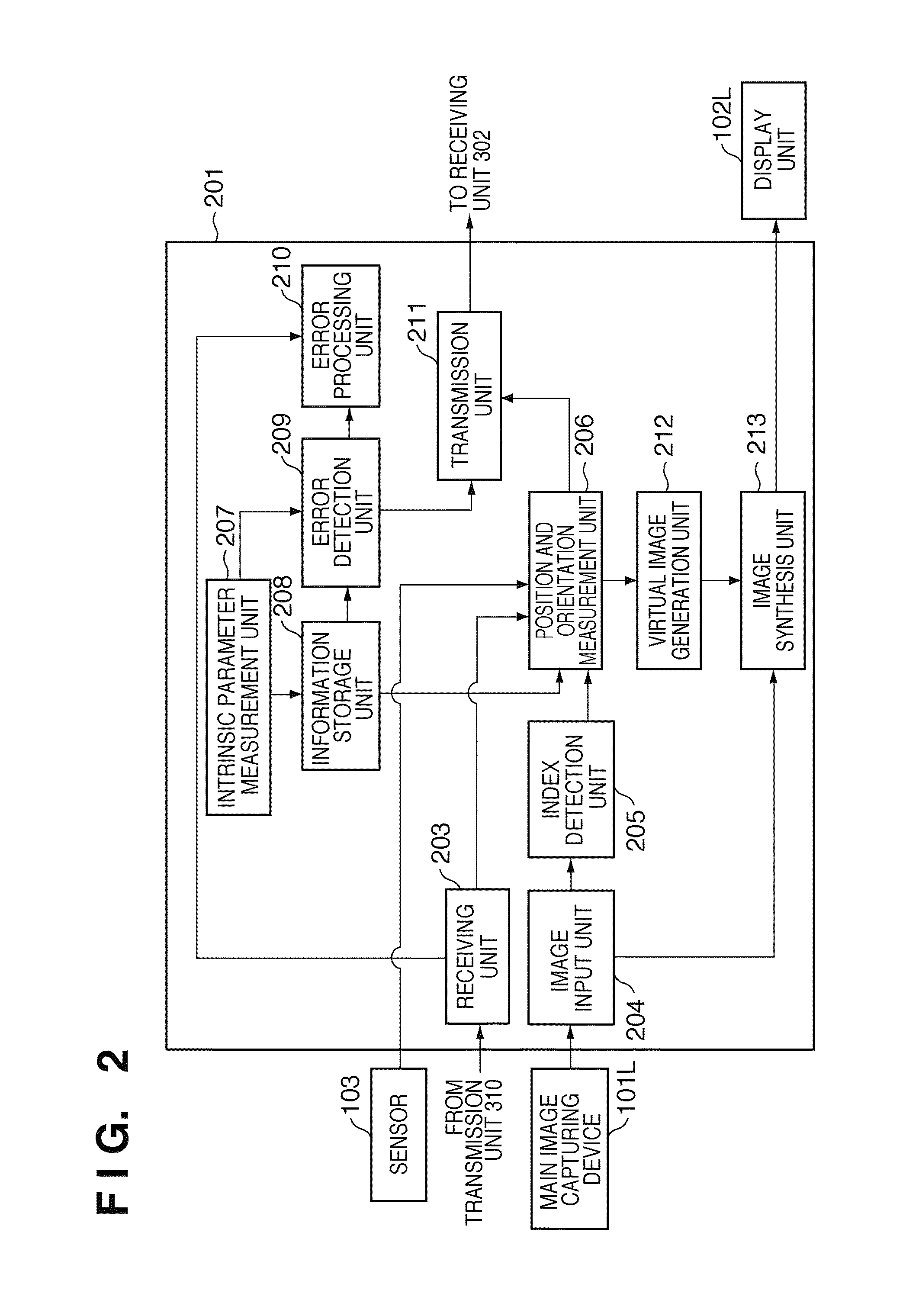
[0029]FIG. 1A is a view illustrating a state when the user wears a stereo video see-through HMD 100 (to be simply referred to as an HMD 100 hereinafter). The HMD 100 has an outer appearance shape similar to spectacles or goggles, and right- and left-eye display units 102R and 102L including, for example LCDs are arranged inside the HMD. In order to acquire a stereo video image, a main image capturing device 101L as a first image capturing device which serves as a left-eye video camera is arranged in the vicinity of the left-eye viewpoint position of the user (who wears the HMD) in the HMD 100. Likewise, a sub image capturing device 101R as a second image capturing device which serves as a right-eye video camera is arranged in the vicinity of the right-eye viewpoint position of the HMD 100. The main image capturing device 101L and sub image capturing device 101R include, for example, CCD cameras, and capture images of a real world. A position and orientation sensor 103 is used to det...

second embodiment

[0132]In the second embodiment, the validity of inter-device position and orientation information or intrinsic parameters is determined using edges included in images obtained from respective image capturing devices. The second embodiment will be described below with reference to the flowchart shown in FIG. 10. The left side of the vertical dotted line of the flowchart shows the processing sequence of a main information processing apparatus 201, and the right side shows that of the sub information processing apparatus 301.

[0133]In steps 1001 and 1002, an error detection unit 209 of the main information processing apparatus 201 and an error detection unit 308 of the sub information processing apparatus 301 extract edges from images captured by a main image capturing device 101L and sub image capturing device 101R. Assume that an edge is, for example, a point where densities change abruptly in an image.

[0134]In step 1003, the error detection unit 308 of the sub information processing ...

third embodiment

[0146]FIGS. 11 and 12 are block diagrams showing the arrangements of information processing apparatuses according to the third embodiment. The third embodiment will be described below with reference to FIGS. 11 and 12. FIG. 11 shows the arrangement of a main information processing apparatus 201 connected to a main image capturing device 101L, and FIG. 12 shows the arrangement of a sub information processing apparatus 301 connected to a sub image capturing device 101R. Compared to the arrangements of the first embodiment (FIGS. 2 and 3), a communication direction is only that from the main information processing apparatus 201 to the sub information processing apparatus 301.

[0147]An information storage unit 1108 holds index definition information which defines positions and orientations of indices on a real space. This definition information has to be generated in advance. As the generation method, the definition information may be generated by, for example, manually measuring the pos...


PUM


Abstract

An information processing apparatus, which provides images for stereoscopic viewing by synthesizing images obtained by capturing an image of real space by a main image sensing device and sub image sensing device to a virtual image, measures the position and orientation of the main image sensing device, calculates the position and orientation of the sub image sensing device based on inter-image capturing device position and orientation held in a holding unit and the measured position and orientation of the main image sensing device. Then the information processing apparatus calculates an error using the measured position and orientation of the main image sensing device, the calculated position and orientation of the sub image sensing device, and held intrinsic parameters of the main image sensing device and sub image sensing device. The information processing apparatus calibrates the held information based on the calculated error.

Description

BACKGROUND OF THE INVENTION[0001]1. Field of the Invention[0002]The present invention relates to a calibration technique of camera intrinsic parameters and a relative position and orientation between cameras.[0003]2. Description of the Related Art[0004]Conventionally, a virtual reality (VR) system is known. This VR system presents a three-dimensional computer graphics (CG) image created by a computer to the user to make him or her feel as if a virtual space were a real space. In recent years, a technique for presenting information which does not exist in real space to the user by synthesizing a three-dimensional CG to an image of real space has been developed. This technique is called a mixed reality (MR) system. This MR system aims at coexistence of the for a real space and a virtual space to coexist that can be experienced in only a condition isolated from the real space, and has received a lot of attention as a technique for enhancing virtual space.[0005]As a typical apparatus th...

Claims


Application Information

Patent Timeline
Patent Type & Authority Applications(United States)
IPC IPC(8): H04N13/02H04N13/239G01B11/245G01B21/00G01B21/22G06T1/00G06T19/00H04N5/64H04N7/18
CPCH04N13/0239H04N13/044H04N13/0278H04N13/239H04N13/279H04N13/344
Inventor MIYATANI, SONOKOMORITA, KENJIFUJIKI, MASAKAZU
Owner CANON KK
Why Eureka
Try Eureka