
LED lamp

a technology of led lamps and led lamps, which is applied in the field of led lamps, can solve the problems of quick rise in temperature of led lamps and unattractive appearance of led lamps

Inactive Publication Date: 2010-11-25
FU ZHUN PRECISION IND SHENZHEN +1
View PDF4 Cites 51 Cited by
  • Summary
  • Abstract
  • Description
  • Claims
  • Application Information

AI Technical Summary

Benefits of technology

[0004]As highly effective light sources, LED lamps are widely used in various fields. An LED lamp includes a number of LEDs, and most of the LEDs are driven at the same time, which results in a quick rise in temperature of the LED lamp. Generally, the LED lamp utilizes a heat sink to dissipate heat generated by the LEDs. A conventional LED lamp includes a rectangular heat dissipation plate and a number of LEDs mounted on a side of the heat dissipation plate. In operation, the heat generated by the LEDs can be quickly dissipated by the heat dissipation plate. However, the rectangular heat dissipation plate causes the LED lamp to be bulky and makes the LED lamp having an unattractive appearance.

Problems solved by technology

An LED lamp includes a number of LEDs, and most of the LEDs are driven at the same time, which results in a quick rise in temperature of the LED lamp.
However, the rectangular heat dissipation plate causes the LED lamp to be bulky and makes the LED lamp having an unattractive appearance.

Method used


Image

  • LED lamp
  • LED lamp
  • LED lamp

Examples


Embodiment Construction

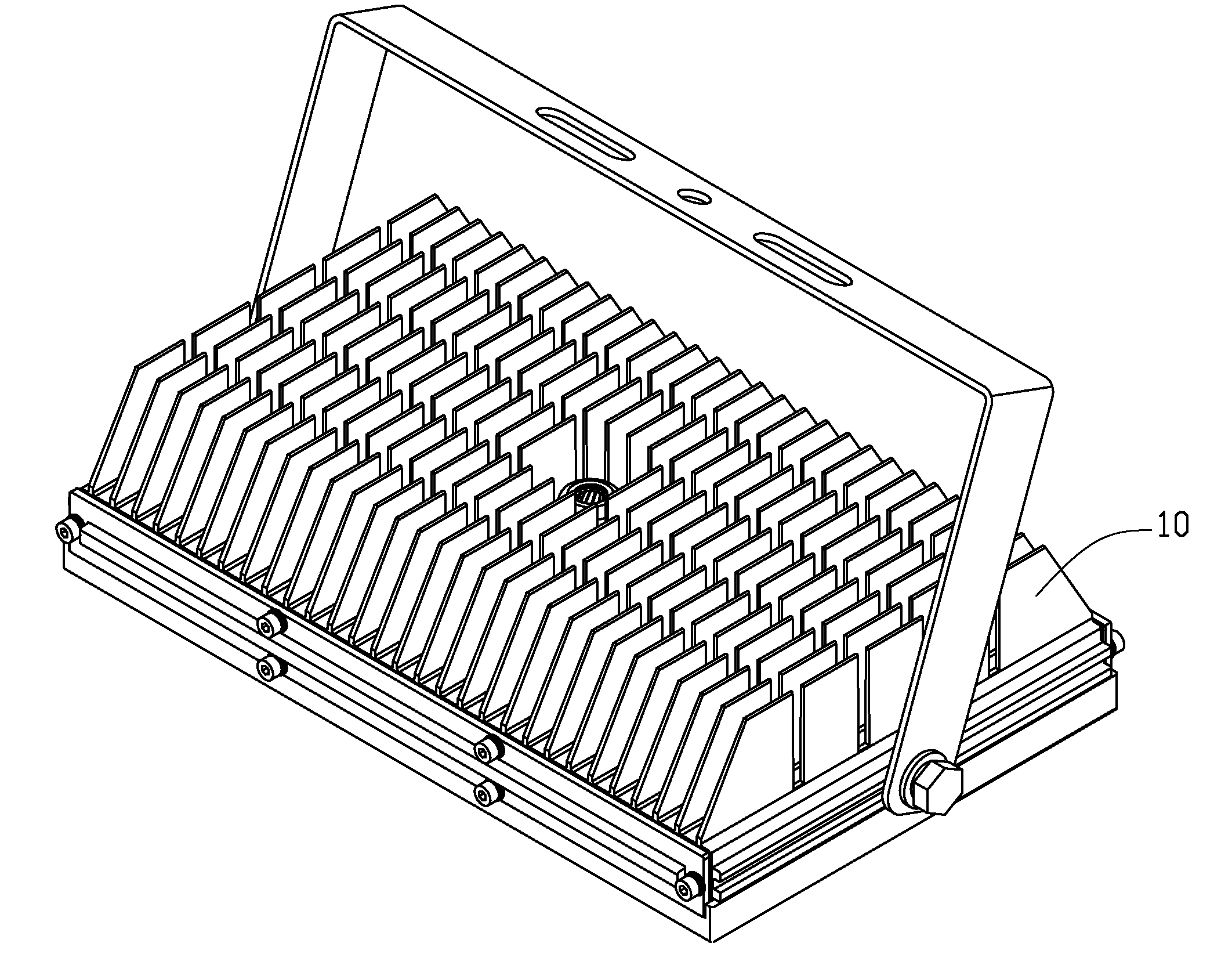
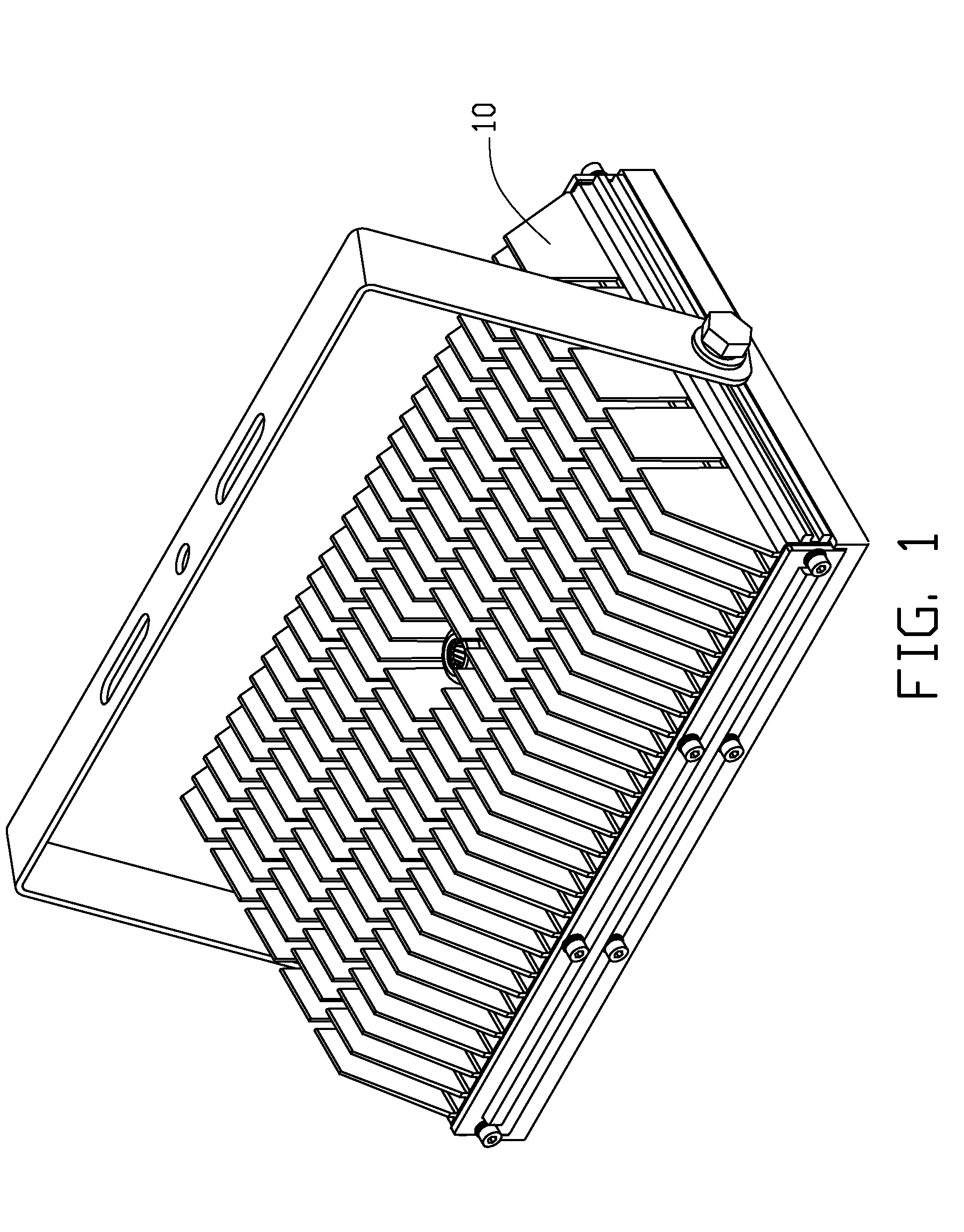
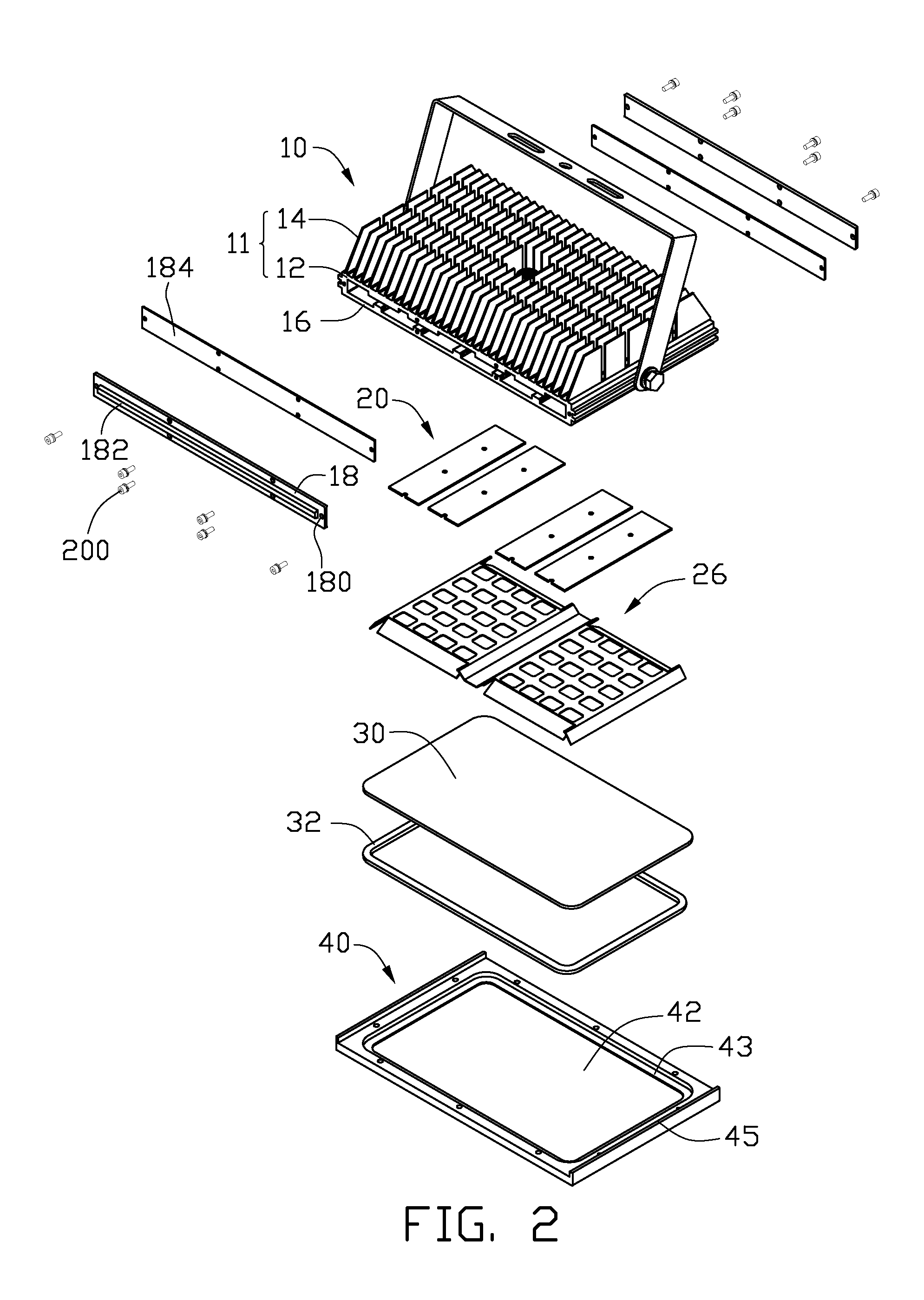
[0010]Referring to FIGS. 1-2, an LED lamp in accordance with an embodiment of the disclosure is illustrated. The LED lamp comprises a housing 10, a plurality of LED modules 20 thermally received in the housing 10, a cover 30 covering the LED modules 20 and a pressing frame 40 securing the cover 30 to the housing 10.

[0011]Referring to FIG. 3 also, the housing 10 is integrally extruded from a metal with a good heat conductivity such as aluminum. The housing 10 comprises a heat sink 11 to which the LED modules 20 are attached and a hollow receiving portion 16 extending downwardly from a bottom of the heat sink 11. The heat sink 11 comprises a planar base 12, a plurality of fins 14 extending upwardly and perpendicularly from a top face of the base 12, and a plurality of rectangular heat-absorbing portions 120 protruding downwardly from a bottom face of the base 12. The heat-absorbing portions 120 are parallel to and spaced from each other. A plurality of threaded holes (not labeled) are...


PUM


Abstract

An LED lamp includes a monolithic housing made of metal extrusion and comprising a heat sink and a receiving portion integrally extending from a bottom of the heat sink, a plurality of LED modules attached to the heat sink, a cover covering the LED modules and a supporting bracket mounted on the housing. The heat sink includes a planar base and a plurality of fins extending from a top face of the base. The receiving portion includes a frame defining a window at a center thereof and two sidewalls interconnecting the frame and the base. The frame, the sidewalls and the base cooperatively define a receiving chamber for accommodating the LED modules therein. The LED modules are attached to the base and located corresponding to the window of the frame. The cover is mounted on a bottom of the frame and correspondingly covers the window.

Description

BACKGROUND[0001]1. Technical Field[0002]The disclosure relates to light emitting diode (LED) lamps and, particularly, to an LED lamp having an improved heat dissipation structure.[0003]2. Description of Related Art[0004]As highly effective light sources, LED lamps are widely used in various fields. An LED lamp includes a number of LEDs, and most of the LEDs are driven at the same time, which results in a quick rise in temperature of the LED lamp. Generally, the LED lamp utilizes a heat sink to dissipate heat generated by the LEDs. A conventional LED lamp includes a rectangular heat dissipation plate and a number of LEDs mounted on a side of the heat dissipation plate. In operation, the heat generated by the LEDs can be quickly dissipated by the heat dissipation plate. However, the rectangular heat dissipation plate causes the LED lamp to be bulky and makes the LED lamp having an unattractive appearance.[0005]What is needed, therefore, is an improved LED lamp which can overcome the a...

Claims


Application Information

Patent Timeline
IPC IPC(8): F21S4/00
CPCF21S6/00F21S8/06F21V15/013F21V21/30F21V29/89F21Y2101/02F21Y2105/001F21V29/75F21V29/763F21V29/004F21Y2105/10F21Y2115/10
Inventor HUANG, XING-GUI
Owner FU ZHUN PRECISION IND SHENZHEN
Learn More