

Rotary-type fluid machine
a fluid machine and rotary-type technology, which is applied in the direction of machines/engines, rotary/oscillating piston pump components, liquid fuel engines, etc., can solve the problems of vibration or noise in reduce and reduce the production cost of the rotary-type fluid machine. , the effect of reducing the vibration or noise of the rotary-type fluid machin
- Summary
- Abstract
- Description
- Claims
- Application Information
AI Technical Summary
Benefits of technology
Problems solved by technology
Method used
Image

Examples
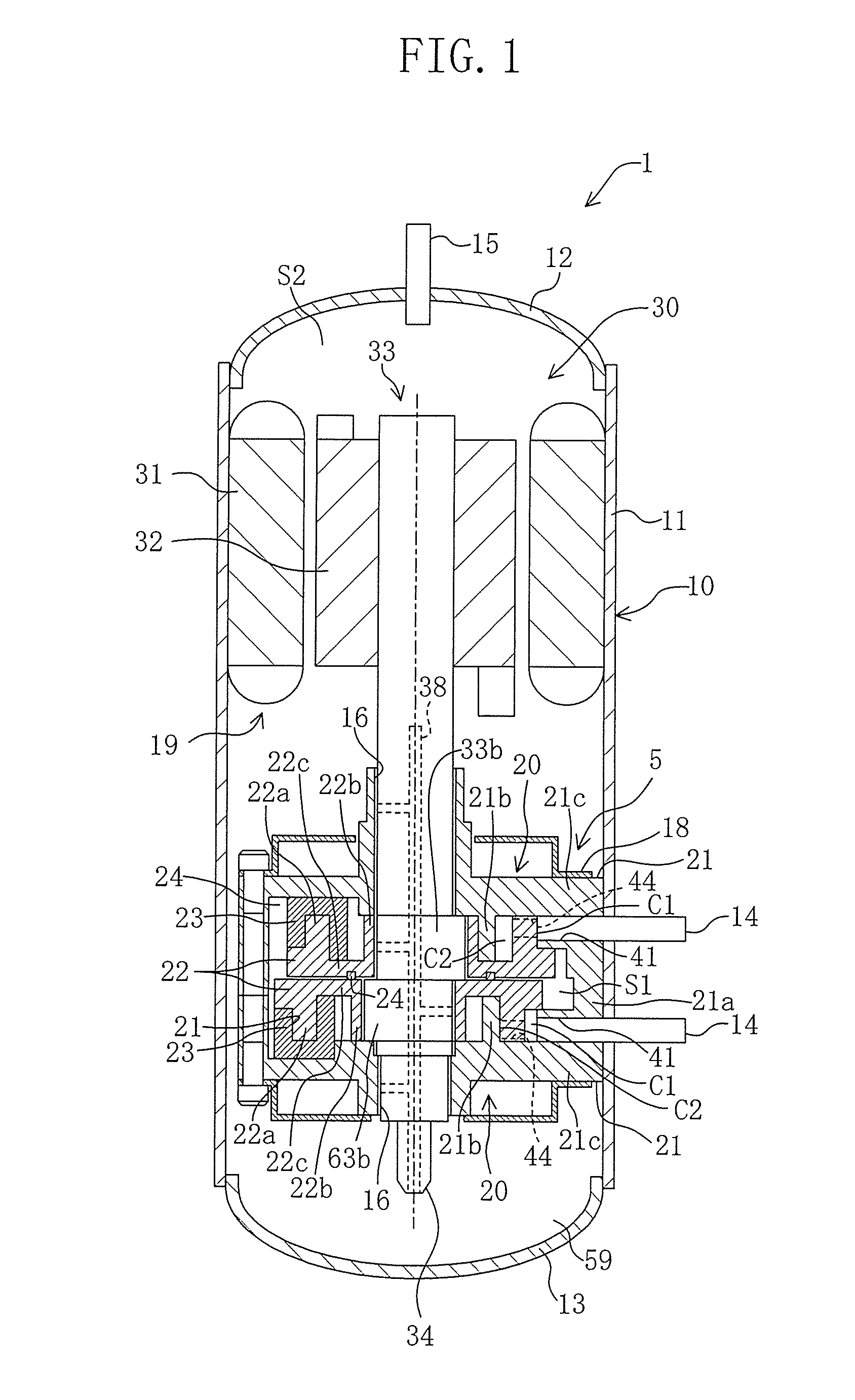
first embodiment
Advantages of First Embodiment
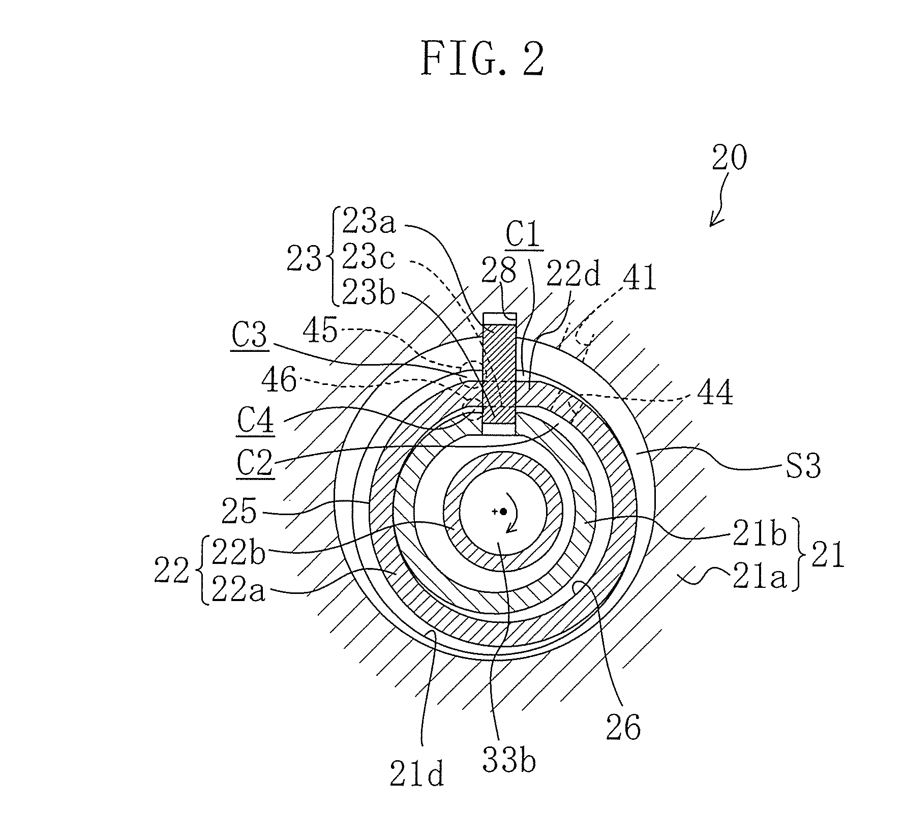
[0089]According to the first embodiment, in the ring-shaped piston (22), the outer circumferential surface (25) and the inner circumferential surface (26) of the piston portion (22a) have the same surface area. Therefore, a load exerted on the ring-shaped piston (22) (a load working on the outer circumferential surface (25)) by the gas pressure inside of the outside compression chamber (C1, C3) can be equalized to a load exerted on the ring-shaped piston (22) (a load working on the inner circumferential surface (26)) by the gas pressure inside of the inside compression chamber (C2, C4).
[0090]Here, the output torque of the drive shaft (33) is determined by the load working on the ring-shaped piston (22). Accordingly, the load working on the outer circumferential surface (25) is equalized to the load working on the inner circumferential surface (26), and thereby, the variations in the output torque of the drive shaft (33) by each compression portion (20) ...
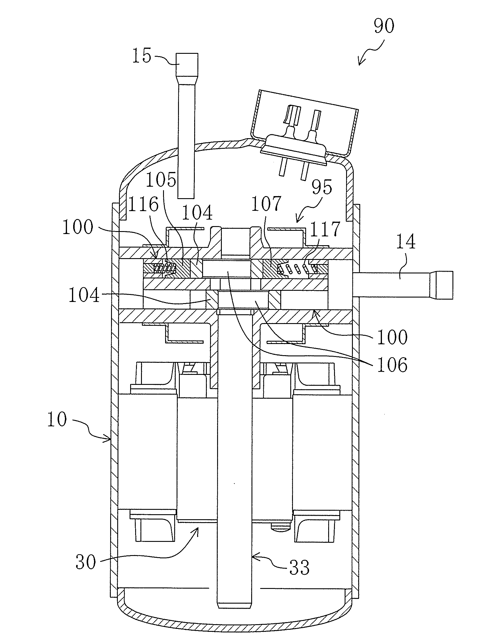
second embodiment
Advantages of Second Embodiment
[0104]According to the second embodiment, each compression portion (100) is of a multi-vane type. Therefore, as compared with the first embodiment, a load exerted on the piston (104) (a load working on the right outer-circumferential wall surface (114)) by the gas pressure inside of the first compression chamber (101) can be easily equalized to a load exerted on the piston (104) (a load working on the left outer-circumferential wall surface (115)) by the gas pressure inside of the second compression chamber (102).
[0105]Specifically, according to the first embodiment, the ring-shaped compression chambers (C1, C2, C3, C4) are formed on the inside and outside of the piston portion (22a), and thereby, the outer circumferential surface (25) and the inner circumferential surface (26) of the piston portion (22a) each have a mutually different length in the circumferential directions. Therefore, in order to equalize the gas pressures working on the outer circu...
PUM
 Abstract
Description
Claims
Application Information