System and method to assist in the braking of an aircraft on a landing runway

a technology for landing runways and aircraft, which is applied in the direction of automatic braking sequences, aircraft braking arrangements, instruments, etc., can solve the problems of affecting the speed of landing, excessive fuel consumption, and difficult phases of taxiing maneuvers in airports today

Active Publication Date: 2010-11-25
THALES SA
View PDF20 Cites 24 Cited by
  • Summary
  • Abstract
  • Description
  • Claims
  • Application Information

AI Technical Summary

Benefits of technology

[0026]Advantageously, again, the position characterizing a runway exit and the maximum speed to take this exit are recovered in the data recovery phase and the speed that the aircraft will have reached on the runway when it has traveled the distance to the exit is calculated in the calculation phase. The calculated speed makes it possible to adapt the braking by comparison with the maximum speed to take the exit. If necessary, this comparison is made visually by the pilot. In one particular

Problems solved by technology

Whether to get to a take-off runway entry from an embarkation point or to get to a debarkation point from a runway exit, the taxiing maneuvers in the airports today constitute difficult phases.
Runway occupancy times for landing that are longer than necessary are a source of waiting delays leading to an excess consumption of fuel for the aircraft in approach phase and a slowing down in the rate of landings.
Runway occupancy times that are longer than necessary are often caused by poor management of the runway exits.
However, optimizing the runway exit is not easy, because there are numerous parameters involved: the state of the surface of the runway, weather conditions, the weight and condition of the aircraft, in particular of the tires and of the braking system.
Furthermore, it is not enough to apply maximum braking to take the first exit, since the brakes can start to overh

Method used


Image

  • System and method to assist in the braking of an aircraft on a landing runway
  • System and method to assist in the braking of an aircraft on a landing runway
  • System and method to assist in the braking of an aircraft on a landing runway

Examples


Embodiment Construction

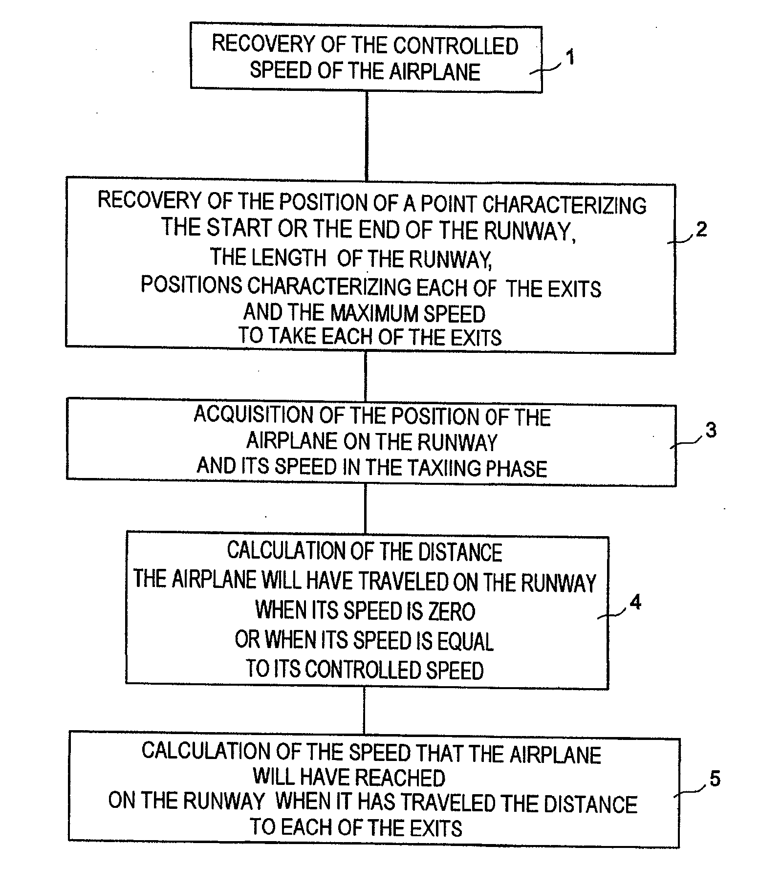
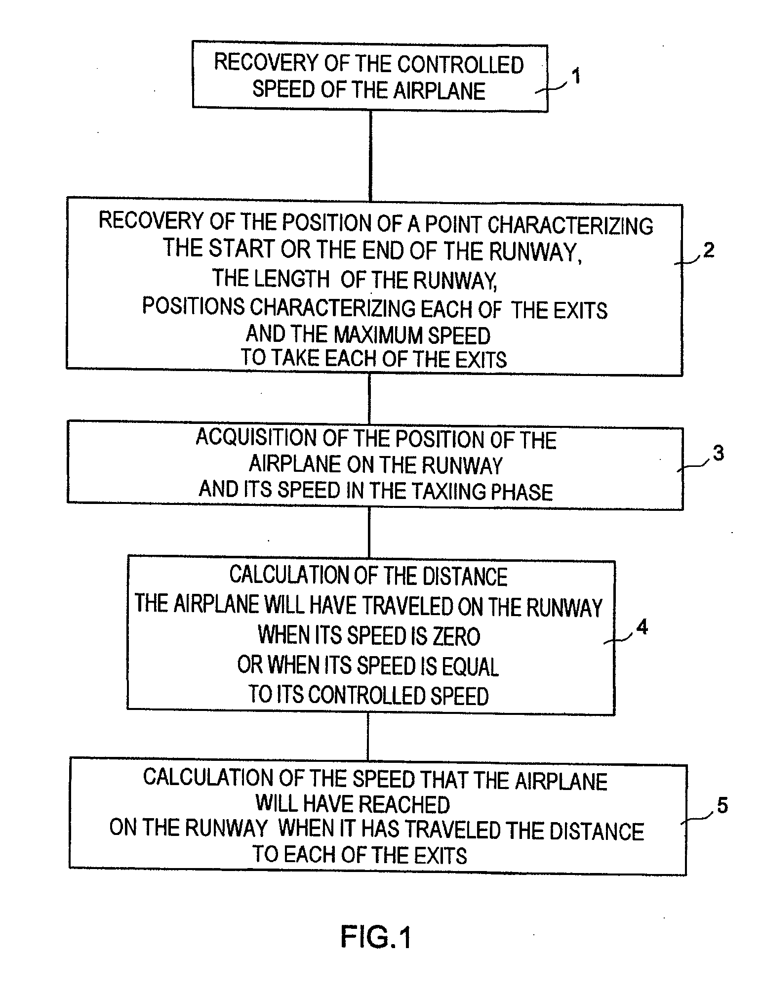
[0034]FIG. 1 illustrates by a flow diagram the possible steps of the method according to the invention.

[0035]It comprises a phase 1 of recovery of the controlled speed of the airplane, which is the speed below which the airplane is capable of performing any maneuver while taxiing. For example, for an airliner it can be of the order of 10 to 20 knots. Trying a demanding maneuver, such as a half-turn for example, above this speed could damage the front landing gear or even result in loss of control of the airplane. Only undemanding maneuvers, such as gentle turns, can be undertaken without risk above this speed. The controlled speed depends on the type of airplane and, generally, the controlled speed reduces as the weight of the airplane increases.

[0036]The method also includes a phase 2 of recovery of the position of a point characterizing the start or the end of the runway, the length of the runway, positions characterizing each of the exits from the runway and the maximum speed to ...


PUM


Abstract

A system includes a means of acquiring the position of the aircraft on the runway and its speed in the taxiing phase, a means of storing data concerning the runway and a predefined deceleration law, a function for calculating the distance that the aircraft will have traveled on the runway when it has reached a certain speed and/or the speed that it will have reached when it has traveled a certain distance: the calculated distance makes it possible to adapt the braking by comparison with the distance remaining to reach the end of the runway; the calculated distance makes it possible to adapt the braking by comparison with the distance remaining to reach the end of the runway; the calculated speed makes it possible to adapt the braking by comparison with the maximum speed to take the exit.

Description

CROSS REFERENCE TO RELATED APPLICATIONS[0001]The present application is a Divisional of U.S. application Ser. No. 11 / 619,600, filed on Jan. 3, 2007, which is based on and claims priority from French Application Number 06 00029, filed on Jan. 3, 2006, the disclosures of which are hereby incorporated by reference herein in there entirety.Field of the Invention[0002]The present invention relates to a system and a method to assist in the braking of an aircraft on a landing runway.BACKGROUND OF THE INVENTION[0003]With the growth of air traffic, the aircraft ground traffic in airport areas is considerably intensified. Whether to get to a take-off runway entry from an embarkation point or to get to a debarkation point from a runway exit, the taxiing maneuvers in the airports today constitute difficult phases.[0004]Various so-called “airport navigation” avionics functions have already been proposed to facilitate the movement on the ground of the aircraft in an airport context.[0005]For exam...

Claims


Application Information

Patent Timeline
IPC IPC(8): G06F19/00
CPCG05D1/0083B64C25/426G08G5/065
Inventor HUGUES, MEUNIER
Owner THALES SA
Why Eureka
Try Eureka