Swimming pool cleaning device

a cleaning device and swimming pool technology, applied in the field of swimming pools, can solve the problems of ineffective prior art devices for removing debris bits, difficult to capture tree leaves, and inability to capture debris larger than the bottom gap of the device, so as to enhance the capture of debris, minimize the possibility of debris catching, and increase the effect of water flow

Active Publication Date: 2010-12-02
DEWING DAVID
View PDF8 Cites 21 Cited by
  • Summary
  • Abstract
  • Description
  • Claims
  • Application Information

AI Technical Summary

Benefits of technology

[0012]In a preferred embodiment, the housing includes two curved fenders, each attached to the rectangular housing along one of the housing long sides so as to partially wrap around the top of one of the cylindrical rotary brushes and increase water flow through the bottom portion of the brush to enhance capture of debris. The housing bottom preferably also includes sloped edges along each of the housing long sides such that the bottom gap is increased adjacent to the cylindrical rotary brushes to minimize the possibility of debris catching on the outer edge of the housing bottom. Further improvement is preferably provided by a bottom suction cavity and / or channels designed to channel debris toward the suction hole bottom entrance, which is preferably beveled so as to avoid a sharp suction hole rim that could trap debris.

Problems solved by technology

Such devices are reasonably effective for removing dirt from the pool bottom but cannot capture debris larger than the bottom gap of the device.
Such brushes tend to push debris along the pool bottom rather than direct it to the suction hole.
Such prior art devices are ineffective for removing bits of debris that are too large to pass through the narrow bottom gap between the housing bottom perimeter and the pool surface.
Tree leaves are particularly difficult to capture using the devices of the prior art since the leaves are often highly non-planar so that they do not readily pass through the small bottom gap needed to vacuum dirt from pool surfaces.
The Sebor '275 device is relatively complicated and does not provide continuous capture of debris.
The Parenti '800 device is relatively complicated and is not well suited for use in small residential swimming pools.
This device is relatively complicated and is not well suited for use in small residential swimming pools.
Consequently, rotary brushes incorporated in prior art devices have typically been located within the suction cavity where they are ineffective as aids for capturing debris too large to directly pass through the bottom gap of the device.
Prior art pool cleaning devices also tend to be powered by an electric or hydraulic motor and often include steering mechanisms, making them too bulky, complicated and expensive for use in small residential swimming pools.

Method used


Image

  • Swimming pool cleaning device
  • Swimming pool cleaning device
  • Swimming pool cleaning device

Examples


example 1

Preliminary Tests

[0046]For preliminary tests of the invention, a commercial pool cleaning device having four cantilevered crossbeams with eight transport wheels attached to the ends thereof was modified by installing three cylindrical brushes (one-inch diameter with brass bristles) between the four transport wheels along each side of the housing, as depicted in FIG. 5. The three cylindrical brushes and the four transport wheels along each side of the housing shared a common axle so that the brushes were directly driven and rotated at the same rate and in the same direction as the transport wheels. The modified pool cleaning device was found to be more effective than the unmodified device for capturing tree leaves but the tests indicated that a faster brush rotation rate and / or a larger brush diameter might be beneficial.

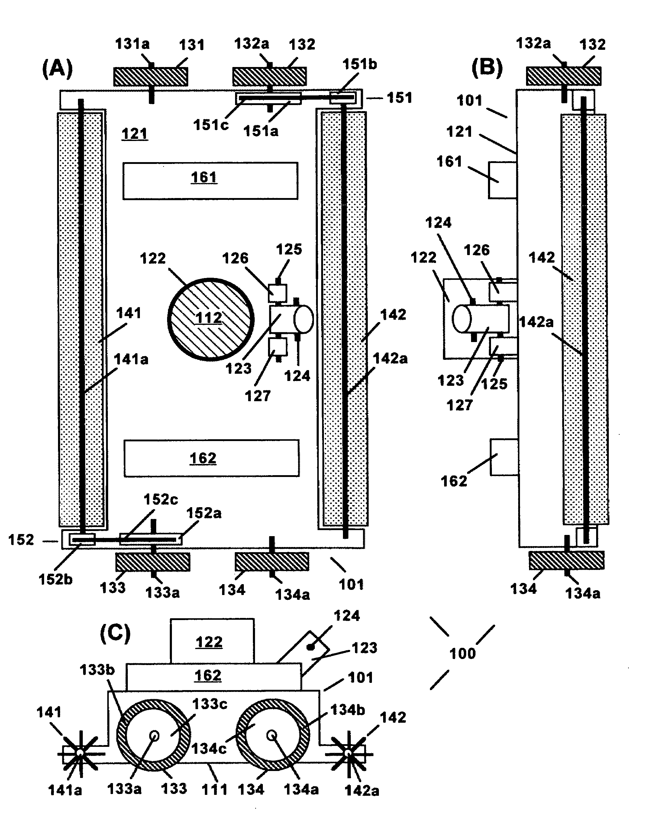
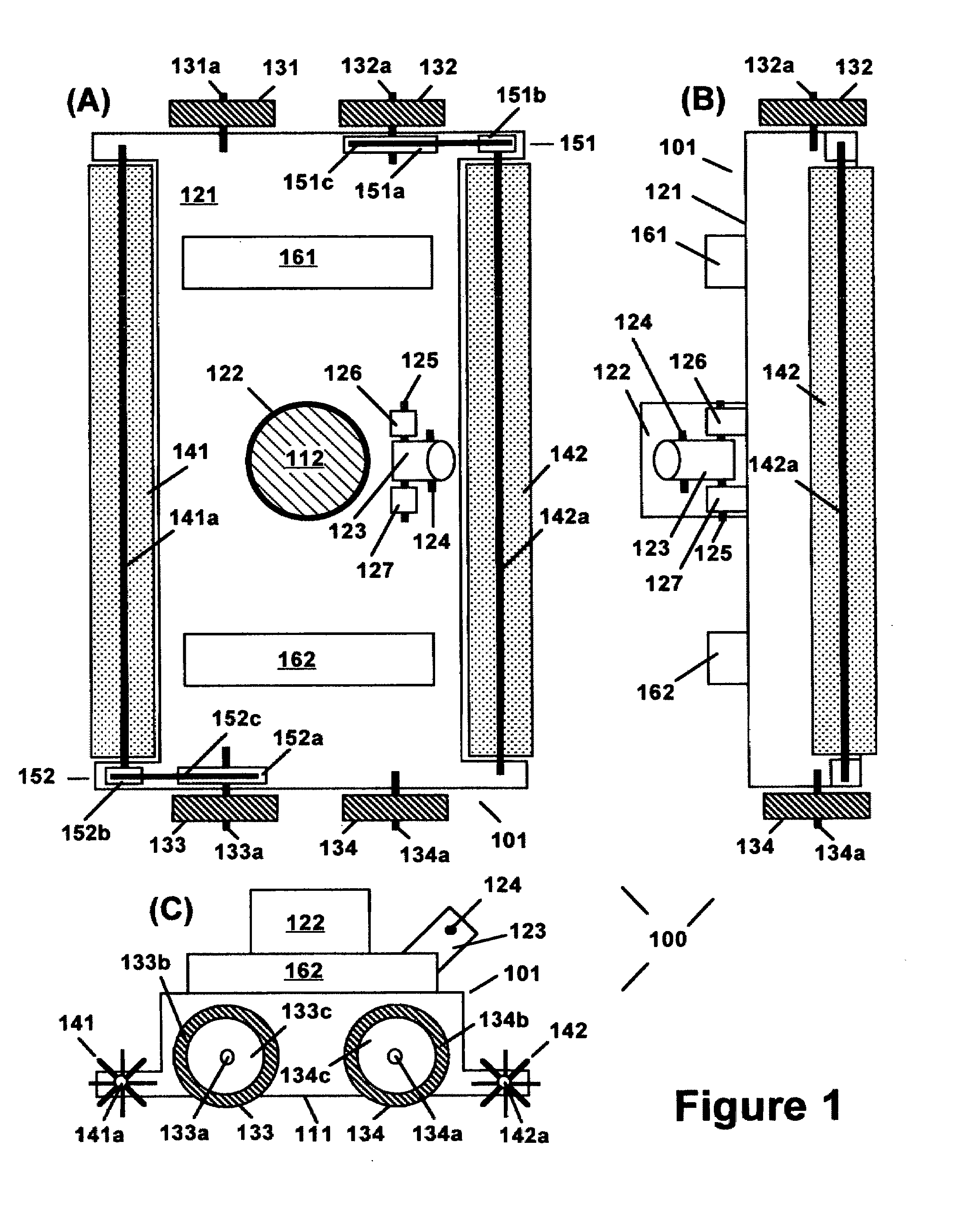
[0047]As depicted in FIGS. 2 and 3, a preferred pool cleaning device according to the invention comprises a rectangular housing with a beveled suction hole and two t...

example 2

Prototype Pool Cleaning Device

[0048]A prototype pool cleaning device according to the invention was designed and is under construction. The rectangular housing of the prototype device is approximately 51 cm wide (long side not including the transport wheels), 19 cm long and 3.5 cm tall (not including the hose connection which extends 2.6 cm above the top of the housing). The suction hole has an inside diameter of 4.6 cm. The prototype housing will be constructed of a resin photopolymer (mechanically similar to ABS and BPT plastics) using a computer-controlled laser polymerization process. A more flexible material is preferred for production devices.

[0049]The four transport wheels of the prototype device are 2.5 cm wide and have an overall diameter of 5.0 cm (including a non-marking tire about 1.0 cm thick), and are each attached to the housing via a transport wheel axle (1.5 cm diameter) and a plastic bushing. The four recessed support wheels are 1.3 cm wide and have an overall diam...


PUM


Abstract

The swimming pool cleaner of the invention is a suction device comprising a rectangular housing, at least four wheels enabling the device to be manually rolled along the swimming pool bottom with the long sides perpendicular to the direction of motion, and two cylindrical rotary brushes adjacent and parallel to opposing long sides of the housing and driven by rotation of the device wheels. Tree leaves and other debris are effectively captured due to a downward sweeping action produced by rotation of the cylindrical rotary brush on the leading edge as the cleaning device, connected to a suction means, is rolled back and forth over the swimming pool bottom by an operator pulling and pushing on a pole attached to the top of the housing. The performance of the device is enhanced via fenders that wrap around the tops of the rotary brushes, and inclusion of various housing bottom features.

Description

BACKGROUND OF THE INVENTION[0001]1. Field of the Invention[0002]This invention is concerned with swimming pools, and in particular with means of cleaning and removing debris from swimming pools.[0003]2. Description of the Related Art[0004]Swimming pool suction cleaning devices of the prior art typically comprise a rectangular housing having a substantially planar bottom with a centrally located suction hole connected to a suction means via a hose attached to a tubular outlet on the housing top. The cleaning device is moved along the pool bottom so that the housing bottom remains substantially parallel and in close proximity with the bottom of the swimming pool while water from the swimming pool is sucked through a small bottom gap between the housing bottom and the swimming pool bottom. In some cases, wheels or housing bottom protrusions are used to provide a bottom gap that is more uniform and / or optimum in width. The housing may also be made of a flexible material so that the hous...

Claims


Application Information

Patent Timeline
Patent Type & Authority Applications(United States)
IPC IPC(8): A47L9/00
CPCE04H4/1609
Inventor DEWING, DAVID
Owner DEWING DAVID
Why Eureka
Try Eureka