Reel based closure system

a technology of lace and closure, applied in the direction of fastenings, press-button fasteners, footwear, etc., can solve the problems of affecting the performance of some sports, slack and other parts of the lace are in tension, and the tightening force is not evenly distributed

Active Publication Date: 2010-12-02
BOA TECHNOLOGY
View PDF99 Cites 175 Cited by
  • Summary
  • Abstract
  • Description
  • Claims
  • Application Information

AI Technical Summary

Benefits of technology

[0017]According to another embodiment of the footwear lacing system, a spool and lace unit is provided for use in conjunction with a footwear lacing system comprises a spool having ratchet teeth disposed on its periphery configured to interact with a pawl for inhibiting relative rotation of the spool in at least one direction, and a lace securely attached to the spool. Optionally, the lace can be formed of a lubricious polymer having a relatively low elasticity and high tensile strength. Alternatively, the lace can be formed of a multi-strand polymeric cable. Alternatively, the lace can be formed of a multi-strand metallic cable, preferably with a lubricious polymer casing.

Problems solved by technology

A number of drawbacks are associated with this type of lacing system.
First, laces do not adequately distribute the tightening force along the length of the threaded zone, due to friction between the lace and the eyelets, so that portions of the lace are slack and other portions are in tension.
This is uncomfortable and can adversely affect performance in some sports.
Another drawback associated with conventional laces is that it is often difficult to untighten or redistribute tension on the lace, as the wearer must loosen the lace from each of the many eyelets through which the laces are threaded.
The lace is not easily released by simply untightening the knot.
This is especially tedious if the number of eyelets is high, such as in ice-skating boots or other specialized high performance footwear.
Although buckles may be easily and quickly tightened and untightened, they also have certain drawbacks.
This is undesirable in many circumstances, such as for the use of sport boots where the wearer desires a force line that is evenly distributed along the length of the foot.
Another drawback of buckles is that they are typically only useful for hard plastic or other rigid material boots.
Buckles are not as practical for use with softer boots, such as ice skates or snowboard boots.

Method used


Image

  • Reel based closure system
  • Reel based closure system
  • Reel based closure system

Examples


Embodiment Construction

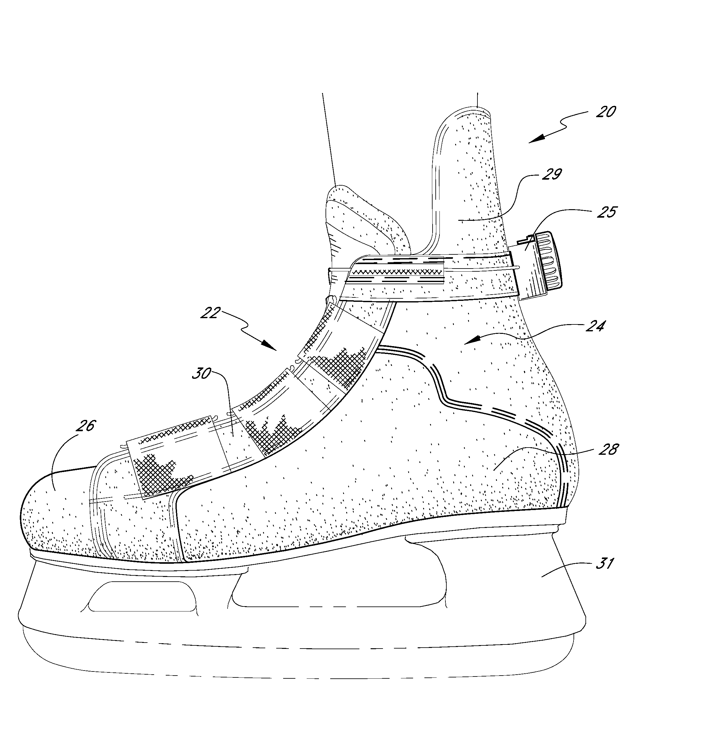
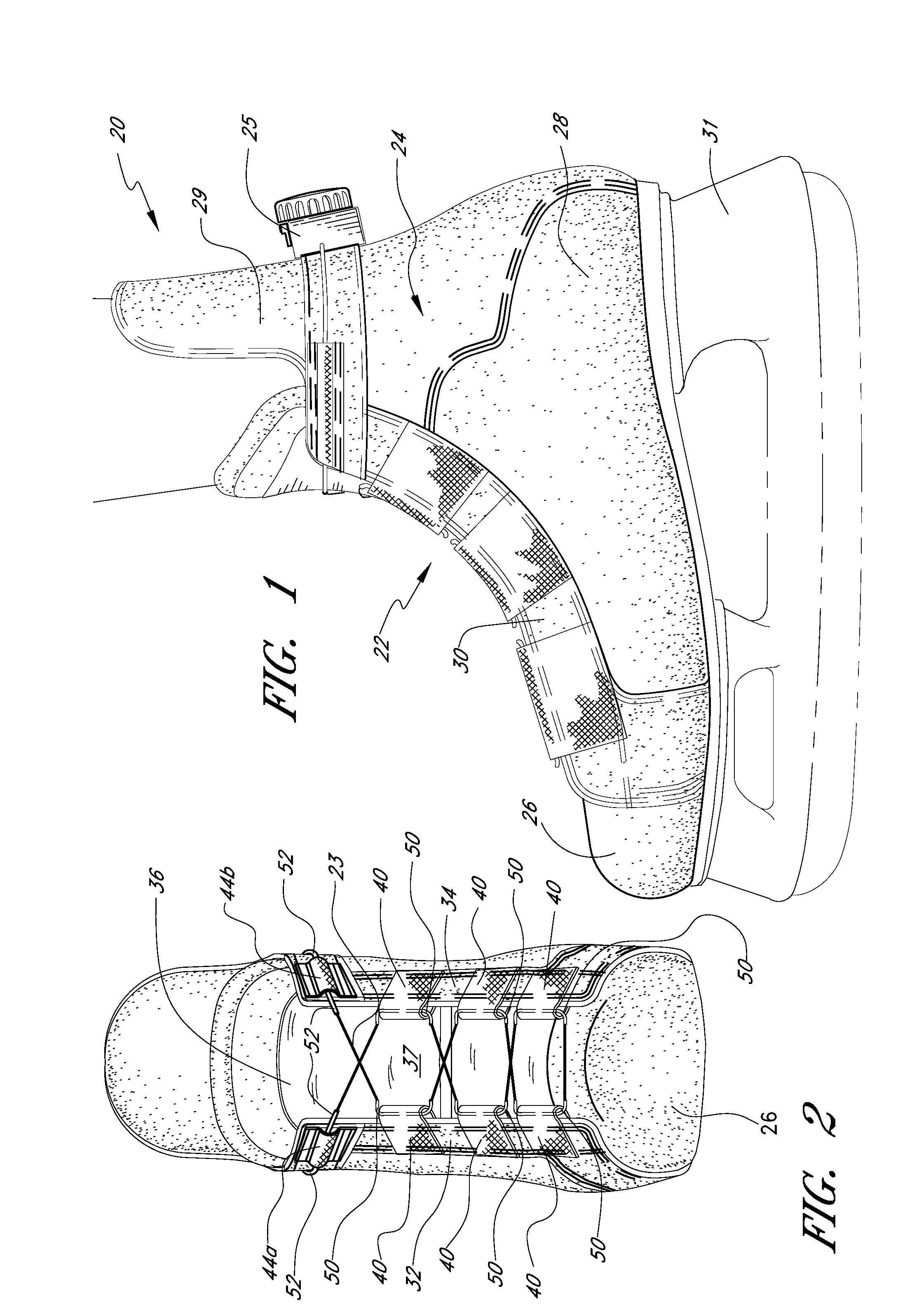
[0077]Referring to FIG. 1, there is disclosed one embodiment of a sport boot 20 prepared in accordance with the present invention. The sport boot 20 generally comprises an ice skating or other action sport boot which is tightened around a wearer's foot using a lacing system 22. The lacing system 22 includes a lace 23 (FIG. 2) that is threaded through the boot 20 and attached at opposite ends to a tightening mechanism 25, as described in detail below. As used herein, the terms lace and cable have the same meaning unless specified otherwise. The lace 23 is a low friction lace that slides easily through the boot 20 and automatically equilibrates tightening of the boot 20 over the length of the lacing zone, which generally extends along the ankle and foot. Although the present invention will be described with reference to an ice skating boot, it is to be understood that the principles discussed herein are readily applicable to any of a wide variety of footwear, and are particularly appl...


PUM


Abstract

Disclosed is a closure system used in combination in any of a variety of applications including clothing, for example as a footwear lacing system comprising a lace attached to a tightening mechanism. The lace extends through a series of guide members positioned along two opposing footwear closure portions. The lace and guides preferably have low friction surfaces to facilitate sliding of the lace along the guide members so that the lace evenly distributes tension across the footwear member. The tightening mechanism allows incremental adjustment of the tension of the lace. The closure system allows a user to quickly loosen the lace and inhibits unintentional and / or accidental loosing of the lace.

Description

CROSS-REFERENCE TO RELATED APPLICATIONS[0001]This application is a continuation of U.S. patent application Ser. No. 11 / 263,253, filed Oct. 31, 2005, pending, which claims the benefit of U.S. Provisional Patent Application No. 60 / 623,341, filed Oct. 29, 2004, and U.S. Provisional Patent Application No. 60 / 704,831, filed Aug. 2, 2005.Incorporate by Reference[0002]This application hereby incorporates by reference U.S. patent application Ser. No. 11 / 263,253, filed Oct. 31, 2005; U.S. patent application Ser. No. 10 / 459,843 filed Jun. 12, 2003, issued as U.S. Pat. No. 7,591,050 on Sep. 22, 2009; U.S. patent application Ser. No. 09 / 993,296 filed Nov. 14, 2001, published as U.S. Patent Publication No. 2002 / 0095750 on Jul. 25, 2002; U.S. patent application Ser. No. 09 / 956,601 filed on Sep. 18, 2001; U.S. Pat. No. 6,289,558, issued Sep. 18, 2001; U.S. Pat. No. 6,202,953, issued Mar. 20, 2001; U.S. Pat. No. 5,934,599, issued Aug. 10, 1999; U.S. Provisional Application No. 60 / 623,341, filed Oct...

Claims


Application Information

Patent Timeline
Patent Type & Authority Applications(United States)
IPC IPC(8): A43C11/00
CPCA43B5/1666A43C1/00Y10T24/2183A43C11/16A43C11/165A43C1/003A43B5/16A43C11/004A43C11/008Y10T24/375Y10T24/3768A43C1/04A43C11/00
Inventor HAMMERSLAG, GARY R.MAYBERRY, MIKESODERBERG, MARK
Owner BOA TECHNOLOGY
Why Eureka
Try Eureka