
Remote control cam locking system

a remote control and cam locking technology, applied in anti-theft devices, construction fastening devices, transportation and packaging, etc., can solve the problems of no commercially, economically installed, viable systems, and often not adapted to commercial vehicle security, and achieves convenient and economical manufacturing, easy and convenient locking and unlocking of multiple compartment doors, and fewer working components.

Inactive Publication Date: 2010-12-02
CAPPUCCIO LOUIS W +1
View PDF25 Cites 21 Cited by
  • Summary
  • Abstract
  • Description
  • Claims
  • Application Information

AI Technical Summary

Benefits of technology

[0004]It is another object of the present invention to provide a remote control cam locking system which has relatively few working components and so is easily and economically manufactured.
[0005]It is a further object of the present invention to provide a remote control cam locking system which can be installed both as original equipment on vehicles and as a retrofit on existing vehicles which do not have a remote control locking capability.
[0006]It is another object of the present invention to provide a remote control cam locking system which can readily and easily lock and unlock the doors of multiple compartments in a vehicle with the touch of a single button on one remote control.
[0007]These and other objects are accomplished by the present invention, a remote control locking system which employs a remote transmitter to send a signal to a message control module / signal receiver. This signal is ultimately forwarded to a cam control unit which positions a cam member to lock and unlock a door, using an internal latching system. The cam control unit has a motor which, through appropriate gear mechanism, rotates a drive shaft to control the position of the cam member for locking and unlocking the door. The message control module / receiver, cam control unit, and attendant components can be self-contained units, each unit configured for use on individual cam controlled doors. The system can be installed as original equipment on vehicles, but also is readily adaptable to retrofitting existing vehicles which do not have remote locking capability. The system is most beneficially provided for use on trucks and similar work vehicles with multiple compartments and their respective doors, which need to be locked and locked quickly to protect property within the compartments.

Problems solved by technology

However, many of the systems consist of multiple, complex, components which are integrated into their respective vehicles.
As a result, these systems represent expensive options, especially when purchased from the vehicle manufacturer.
They are usually not adapted for commercial vehicle security.
Significantly, there are no commercially, economically installed, viable systems which are operable on work trucks having a plurality of storage compartments.
Valuable tools and other property are often stolen, when one or more compartment doors are inadvertently left unlocked.
In addition, given that some trucks have many compartments, each with lockable compartment doors, it is sometimes impractical and often inconvenient to manually lock all doors or use separate remotes to lock individual doors.
As to those trucks which do not have remote locks, there is currently no practical means to retro-fit these vehicles so that their multiple compartment doors can be quickly, easily and remotely locked.

Method used


Image

  • Remote control cam locking system
  • Remote control cam locking system
  • Remote control cam locking system

Examples


Embodiment Construction

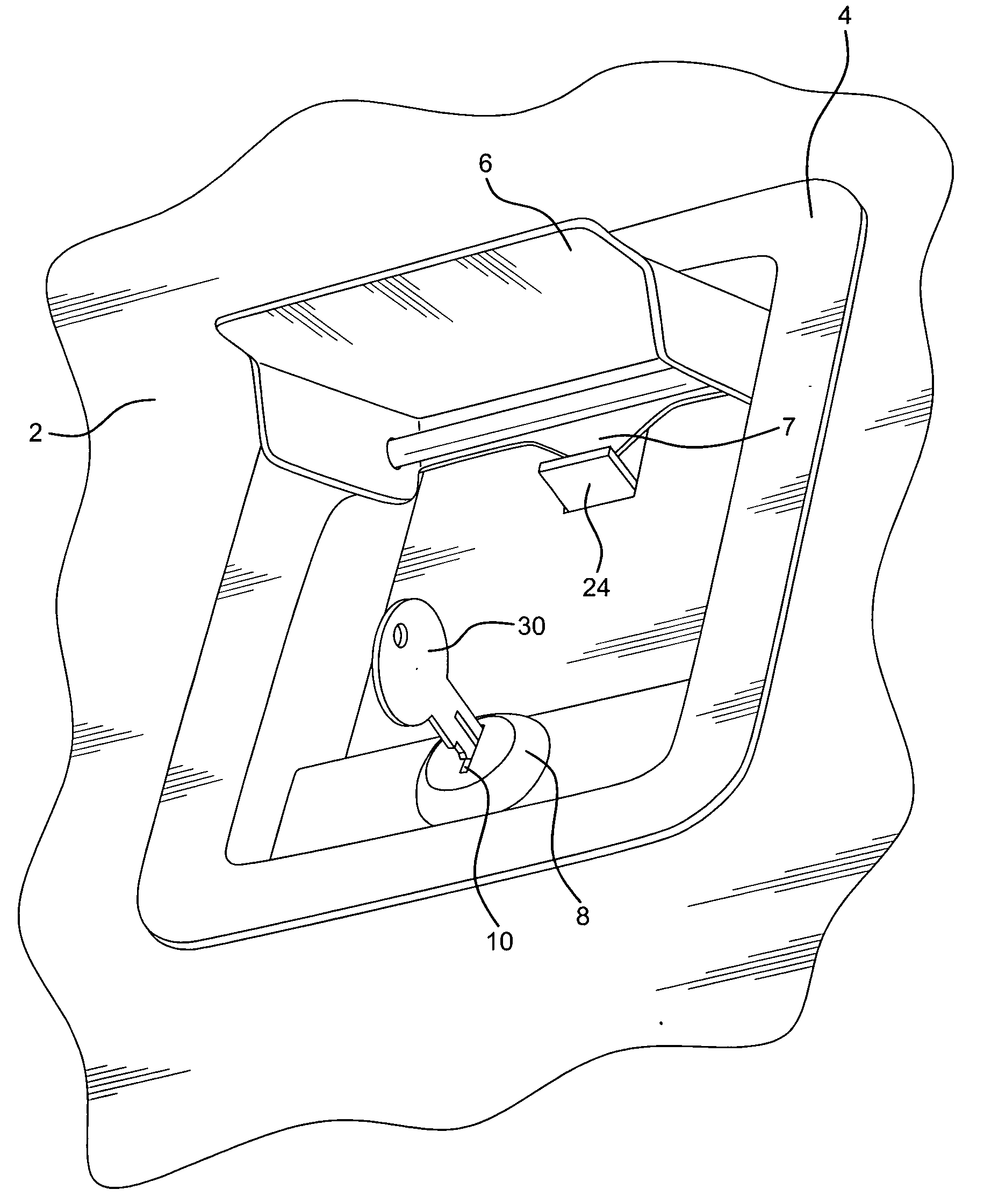
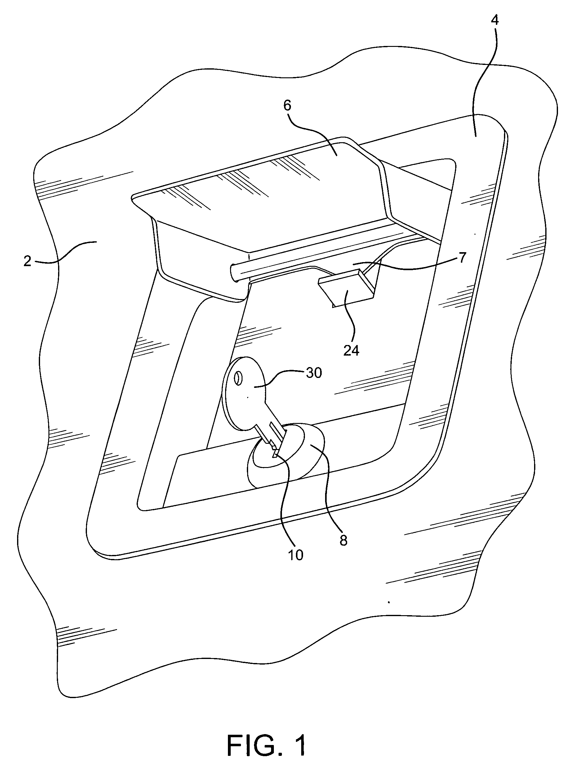
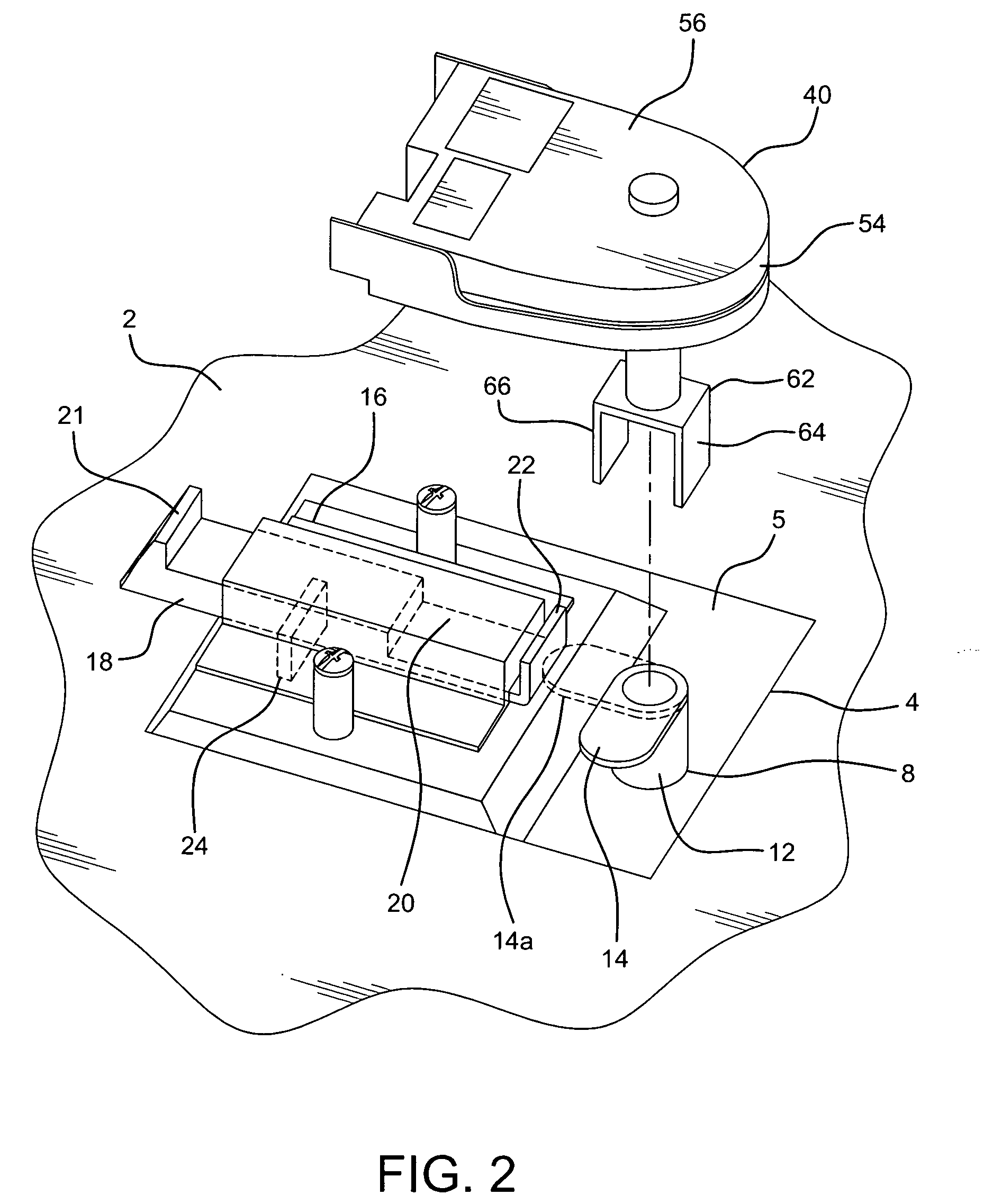
[0013]As seen in FIG. 1, vehicle door 2 comprises handle assembly 4 with spring biased handle 6, pivotable outward, away from the door for opening the door. Lock mechanism 8 with keyway 10 extends through handle assembly 4. FIG. 2 shows a section of the inside of door 2 and inboard side 5 of handle assembly 4. Locking mechanism 8 additionally comprises cam support 12 located on inboard side 5 of handle assembly 4. Cam 14 is mounted on cam support 12. Latch assembly 16 of handle assembly 4, also located on inboard side 5, comprises latch arm 18 slideable within cover 20. Latch connection element 21 is located at one end of arm 18. Latch connection element 21 holds door 2 closed, by corresponding door latch receiving component, not shown or a part of the herein invention. Stop element 22 is located at the other end of latch arm 18. The position of latch arm 18 within cover 20 is controlled by handle 6, which is operably connected to the arm by through arm tab 24 (FIG. 1). Pulling hand...


PUM


Abstract

A remote control locking system employs a remote transmitter which sends a signal to a message control module / signal receiver. This signal is ultimately forwarded to a cam control unit which positions a cam member to lock and unlock a door, using an internal latching system. The cam control unit has a motor which, through appropriate gear mechanism, rotates a drive shaft to control the position of the cam member for locking and unlocking the door. The message control module / receiver, cam control unit, and attendant components can be self-contained units, each unit configured for use on individual cam controlled doors. The system can be installed as original equipment on vehicles, but also is readily adaptable to retrofitting existing vehicles which do not have remote locking capability. The system is most beneficially provided for use on trucks and similar work vehicles with multiple compartments and their respective doors, which need to be locked and locked quickly to protect property within the compartments.

Description

BACKGROUND OF THE INVENTION[0001]Remote vehicle locking systems are well known and various such systems are currently in use at this time. However, many of the systems consist of multiple, complex, components which are integrated into their respective vehicles. As a result, these systems represent expensive options, especially when purchased from the vehicle manufacturer. Moreover, the systems are generally designed to lock and unlock passenger doors on vehicles. They are usually not adapted for commercial vehicle security. Significantly, there are no commercially, economically installed, viable systems which are operable on work trucks having a plurality of storage compartments. It is important that such storage compartments be locked, especially at jobsites, to protect their contents from theft. Valuable tools and other property are often stolen, when one or more compartment doors are inadvertently left unlocked. In addition, given that some trucks have many compartments, each wit...

Claims


Application Information

Patent Timeline
Patent Type & Authority Applications(United States)
IPC IPC(8): E05B65/06
CPCE05B17/2034E05B47/0012E05C1/14E05B2047/0091E05B47/0607Y10T70/5978
Inventor CAPPUCCIO, LOUIS W.COIA, LUKE J.
Owner CAPPUCCIO LOUIS W
Learn More