Heading device

Active Publication Date: 2010-12-02
WAFIOS AKTIENGES
View PDF7 Cites 7 Cited by
  • Summary
  • Abstract
  • Description
  • Claims
  • Application Information

AI Technical Summary

Benefits of technology

[0017]It is again advantageous in a heading device according to the invention if the entire device is attached to a separate framework and is movable thereon in the displacement direction of the shaping ram. This movement axis allows particularly great flexibility during use of the upsetting device, in that, for example, a larger free space can be provided between a bending machine and the heading device according to the invention. However, this simultaneously prevents the workpiece from having to be positioned and/or moved axially relative to the upsetting device in the axial direction before and after the upsetting. This proves to be unfavorable in particular if endles

Problems solved by technology

A hydraulic cold heading device is described in CH-PS 477 929, the device known therefrom having a very large and complicated overall construction, however, in which the use of installing tools is necessary to perform a tool change and the too

Method used


Image

  • Heading device
  • Heading device
  • Heading device

Examples


Embodiment Construction

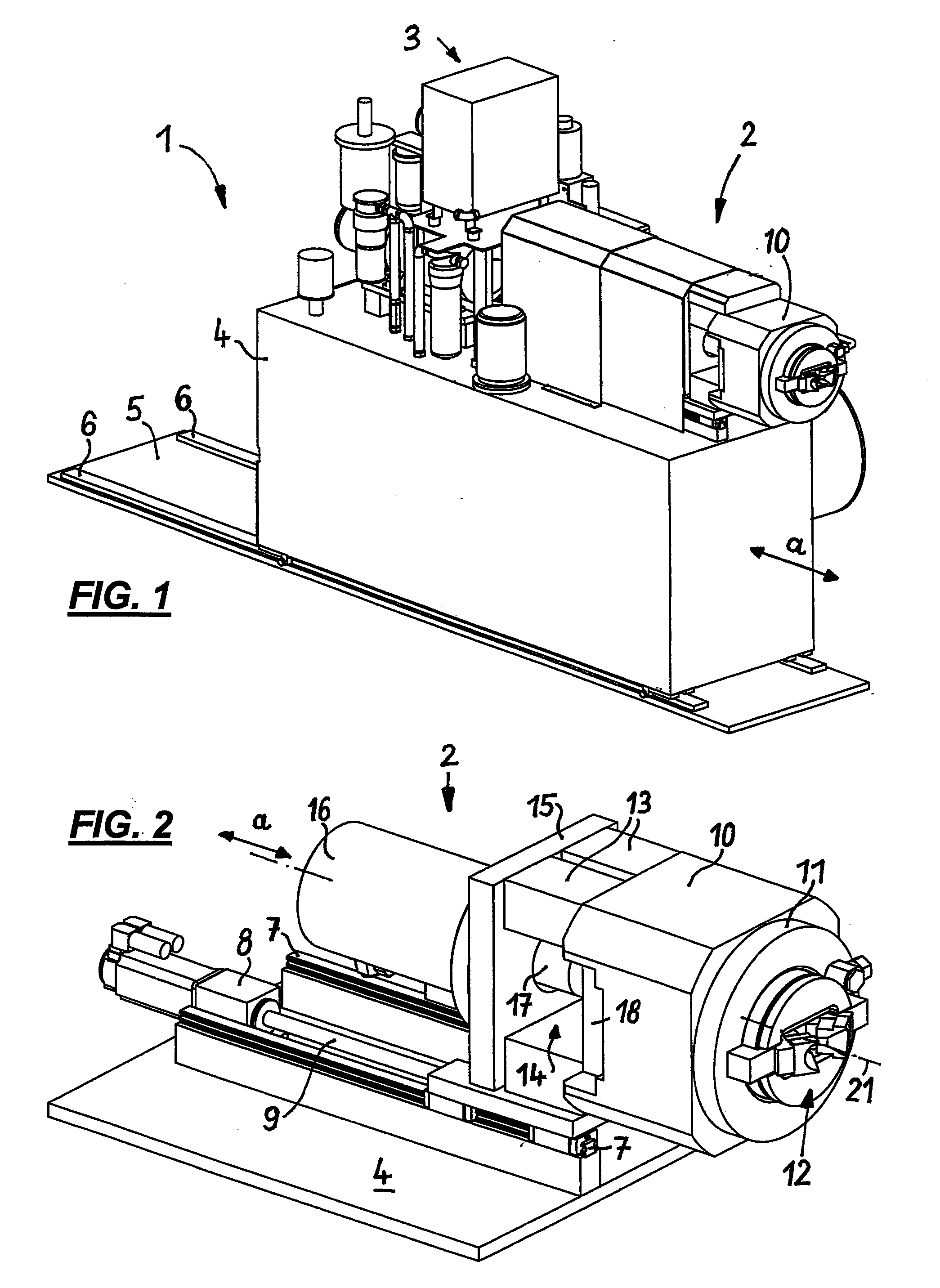
[0025]FIG. 1 shows a perspective view of a heading device 1, which essentially comprises two main parts, namely a shaping unit 2 and a hydraulic unit 3. The latter is a device known per se, which is used for the purpose of providing the required pressures (such as pressing forces up to 600 kN) in the present system.

[0026]The shaping unit 2 and the hydraulic unit 3 are attached on a framework 4, which can in turn be moved or offset along a floor plate 5, in the direction a corresponding to the orientation of the longitudinal axis of the workpieces to be processed and also the longitudinal axis of the shaping unit 2 along guides 6, which are fastened on the floor plate 5.

[0027]A perspective enlarged illustration of the shaping unit 2 is shown in FIG. 2, which is situated on the framework 4, which is only shown, purely schematically, in the form of a common base plate in FIG. 2.

[0028]According to FIG. 2, the shaping unit 2 is seated on the framework 4 on two parallel longitudinal rails...


PUM

PropertyMeasurementUnit
Angleaaaaaaaaaa
Lengthaaaaaaaaaa
Distanceaaaaaaaaaa

Abstract

In a heading device for elongate workpieces having a hydraulic chucking unit and an shaping ram, which is movable axially from a retracted idle position against the workpiece, the chucking unit comprises a housing having a sliding body which is hydraulically displaceable in the axial direction of the workpiece from a starting position into a clamping position (and vice versa), in which at least two chucking segments which are situated uniformly around the workpiece are inserted, which, on their side facing toward the shaping ram, press against a locking plate which is inserted into the housing and can be fixed therein, are movable radially against the workpiece by a displacement of the sliding body in its clamping position, and each receive at least one clamping jaw, which can be pressed by the chucking segment holding it radially against the workpiece for its clamping. The shaping ram carries a forming tool for upsetting the workpiece on the extension side, using which it can be pressed against the head of the workpiece protruding axially from the clamping jaws upon extension through an opening provided in the locking plate, and is moved completely out of the opening in the locking plate with its forming tool in its retracted idle position.

Description

[0001]This application claims priority to German Patent Application No. 10 2009 022 958.2 filed on May 28, 2009, said application is incorporated herein by reference in its entirety.FIELD OF THE INVENTION[0002]The invention relates to a heading device for elongate workpieces, such as bars, pipes, wires, or the like, and it particularly relates to a cold heading device.BACKGROUND OF THE INVENTION[0003]Such heading devices are used for the purpose of shaping the ends of bar-shaped workpieces, i.e., pipe or bar ends, the pipe wall or the bar ends being thickened, up to this point, one or more other local thickened areas (flares) still also additionally being provided in the course of the elongate workpiece by upsetting.[0004]A hydraulic cold heading device is described in CH-PS 477 929, the device known therefrom having a very large and complicated overall construction, however, in which the use of installing tools is necessary to perform a tool change and the tool change itself is rel...

Claims


Application Information

Patent Timeline
IPC IPC(8): B21J5/08B21D41/00
CPCB21J9/06Y10T29/49716Y10T29/5383
Inventor MOCK, JORGTAIGEL, DIRK
Owner WAFIOS AKTIENGES
Why Eureka
Try Eureka