Hands-free cleaning apparatus for roller pads and/or paintbrushes

a technology for cleaning apparatus and roller pads, which is applied in the direction of brushes, cleaning using liquids, coatings, etc., can solve the problems of not providing an adequate solution to the industry needs, and achieve the effects of preventing spillage, facilitating portability of cleaning apparatuses, and facilitating water/paint drained more efficiently

Active Publication Date: 2010-12-02
MCPHEE III WILLIAM JAMES
View PDF49 Cites 15 Cited by
  • Summary
  • Abstract
  • Description
  • Claims
  • Application Information

AI Technical Summary

Benefits of technology

[0009]A hose attachment is also preferably provided to allow the user to attach a water supply hose to the apparatus. The bottom of the apparatus preferably includes a drain hole and legs. The hole allows water / paint to be dispensed as the roller pad is being cleaned. The legs allow the apparatus to be retained a desired distance above a supporting surface, thus allowing water / paint to be drained more efficiently.
[0010]The lid preferably provides numerous functional elements and also preferably seals with the main housing to contain the water / paint remnants and prevent spillage while the apparatus is working. A handle can be a part of the lid to provide easy portability of the cleaning apparatus. A protrusion / extension can be included as part of the lid to seal off the cradle / clip mechanism and further prevent water seepage, and can also act as a stabilizer for the roller bar(s). The lid is preferably connected to the main housing in a way that provides a secure, sealed connection. To provide this, the lid can, for instance, include a female opening that is a part of the lid, which receives a male stub attached to the housing cylinder. This allows the lid and the cylinder to be joined together securely and function as one unit during operation.
[0011]A paintbrush cleaning attachment can also be provided. The paintbrush cleaning attachment can receive a variety of different sizes of paintbrushes and hold them in the cleaning apparatus. When attached in position, water pressure from the stem sprays the brush and causes it to spin. The combination of the spinning and spraying actions serves to effectively clean the brush. The paintbrush attachment can include internal bearings which allow the attachment to spin.
[0012]A cradle and a clip can be provided that enable connection of different size roller bars into the cleaning apparatus. For instance, openings of various diameters can be provided in the cradle and clip and can allow the user to install two or more sizes of roller bars into the cleaning apparatus. The openings are also preferably configured to hold the roller bars in a tight press or interference fit to provide stability for the roller pads being cleaned as they receive high water pressure from the stem.
[0014]In a preferred embodiment, each spray tip is composed of polypropylene and has an opening size encoded “80-15R.” This code represents the size of the hole opening and the amount of water being dispersed from that opening. In addition, the openings can create a water fan that sprays an equal amount of water consistently over the span of the roller pad. Furthermore, in one configuration, the spray direction of each spray tip can be slightly offset from one another outwardly in relation to the surface of the roller pad being cleaned, thus helping to force rotation of the brush being cleaned.

Problems solved by technology

Each of these attempts, however, has suffered from one or more drawbacks and has therefore failed to provide an adequate solution to the industry needs.

Method used


Image

  • Hands-free cleaning apparatus for roller pads and/or paintbrushes
  • Hands-free cleaning apparatus for roller pads and/or paintbrushes
  • Hands-free cleaning apparatus for roller pads and/or paintbrushes

Examples


Embodiment Construction

[0023]According to various principles of the present invention, a hands free cleaning apparatus can be provided for cleaning roller pads, paintbrushes, and / or other painting implements. Numerous embodiments and configurations of the present invention are possible without departing from the core principles of the present invention, each of which will become more apparent through the following detailed description of preferred embodiments.

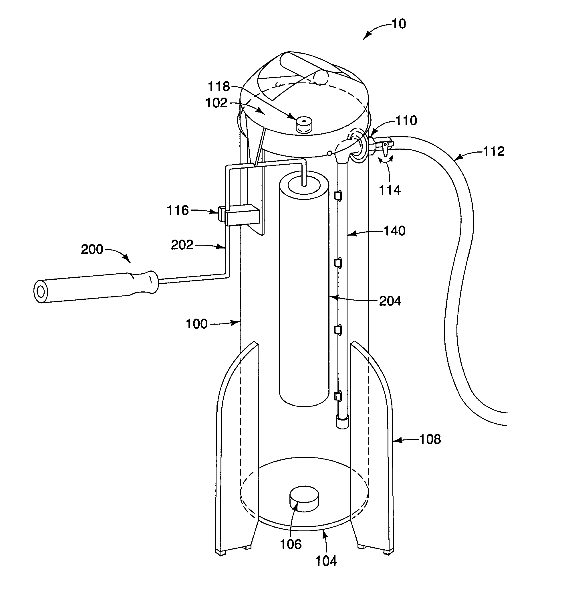
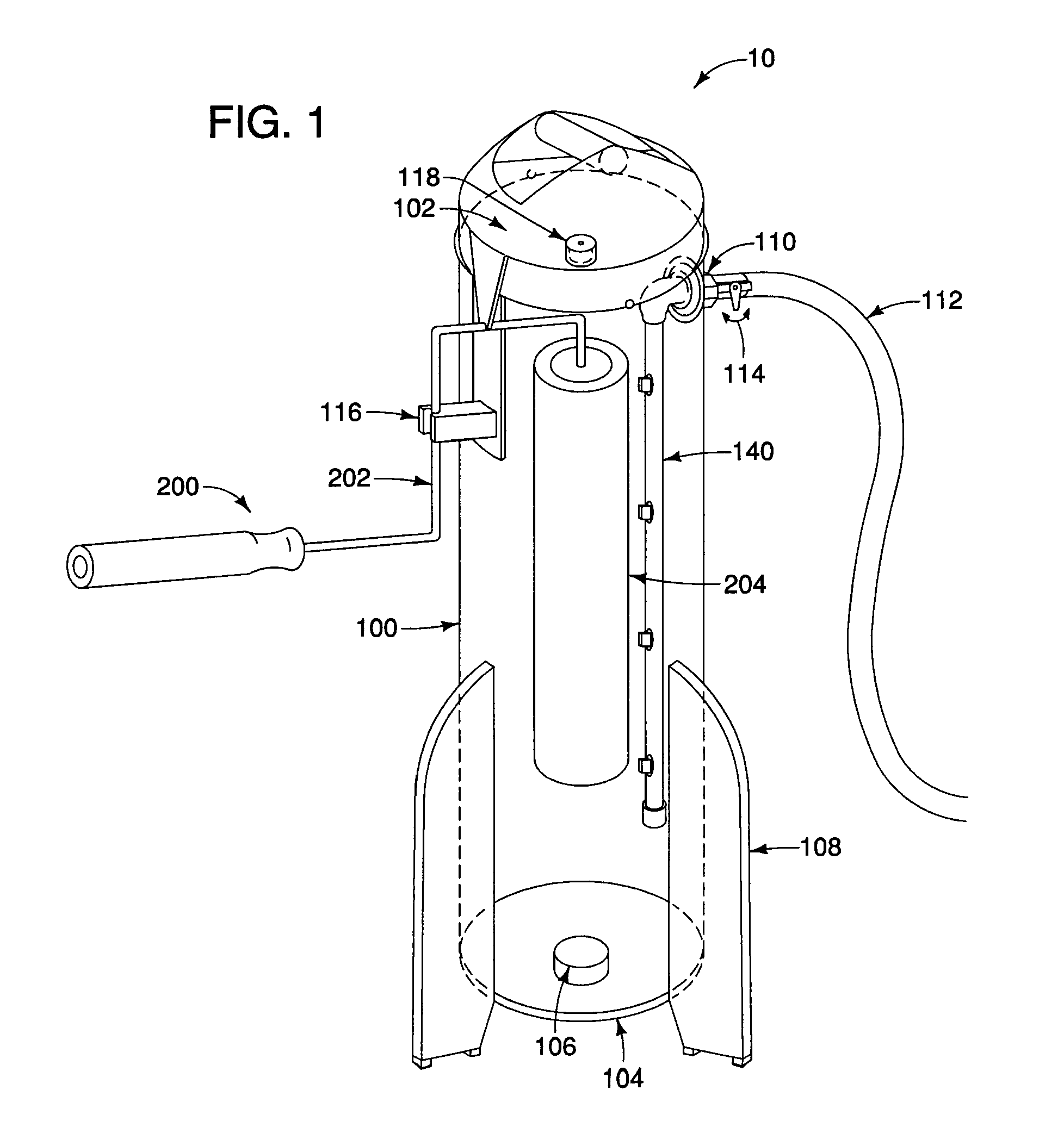
[0024]FIG. 1 is a somewhat schematic perspective view of a hands-free cleaning apparatus 10 according to one potential embodiment of the present invention. Referring to FIG. 1, a hands-free cleaning apparatus 10 can include a main body or housing 100, a lid 102, and a base 104. The body 100 can be a suitably sized cylinder to house the roller pad 204 and / or brush to be cleaned therein. The lid 102 preferably engages the main housing 100 in a secure, sealed relationship to prevent water and paint from leaking out the opening in the top of the housing ...


PUM


Abstract

According to principles of the present invention, a hands-free cleaning apparatus enables a user to clean roller pads of various pad lengths and / or paintbrushes using a single apparatus. In one embodiment, for example, the cleaning apparatus includes a main housing and a lid. An attachment mechanism is preferably provided on the lid or main housing to receive and retain a roller pad or a brush in a desired position and relationship within the cleaning apparatus. A spraying mechanism having one or more spray nozzles is preferably arranged in the housing to spray water (or other cleaning solution) on the pad or brush in a desired manner. A hose attachment can supply water to the apparatus. The spraying mechanism preferably receives water from an attached hose. The spray tips or nozzles are preferably provided at desired locations along the spraying mechanism to provide a desired spray pattern for spinning and cleaning the pad or brush. In one configuration, each spray tip is arranged with a spray direction that is slightly offset from one another in relation to the surface of the roller pad or brush being cleaned, thus helping to force rotation. The bottom of the apparatus can also include a drain hole to allow water and paint to be dispensed as the pad or brush is being cleaned, and legs to support the apparatus a desired distance above a supporting surface, thus allowing water and paint to be drained more efficiently. The lid preferably engages the body in a sealing relationship to prevent spillage during operation of the apparatus. A handle can be a part of the lid to provide easy portability of the cleaning apparatus. A protrusion or extension can also be included as part of the lid to seal off the attachment mechanism and prevent water seepage and to also act as a stabilizer for the roller bar or brush adapter.

Description

PRIORITY INFORMATION[0001]This application is a nonprovisional of, and claims priority from, U.S. Provisional Patent Application Ser. No. 61 / 182,886, filed Jun. 1, 2009, the contents of which are incorporated herein by reference in their entirety.BACKGROUND OF THE INVENTION[0002]1. Field of the invention[0003]This invention relates generally to methods and apparatus for cleaning roller pads and / or paintbrushes. More particularly, this invention relates to a hands-free method and apparatus for cleaning roller pads and / or paintbrushes.[0004]2. Related Art[0005]Various approaches for cleaning roller pads and paintbrushes have been attempted. Some of these are represented, for instance, in U.S. Pat. Nos. 5,839,459; 5,413,133; 5,487,399; 5,626,158; and 5,363,869. Each of these attempts, however, has suffered from one or more drawbacks and has therefore failed to provide an adequate solution to the industry needs.SUMMARY OF THE INVENTION[0006]The principles of this invention overcome the ...

Claims


Application Information

Patent Timeline
Patent Type & Authority Applications(United States)
IPC IPC(8): B08B3/00
CPCA46B17/06B44D3/006B05C17/0245A46B2200/202
Inventor MCPHEE, III, WILLIAM JAMES
Owner MCPHEE III WILLIAM JAMES
Why Eureka
Try Eureka