Power measuring system, measuring apparatus, load terminal, and device control system

a technology of power measurement system and load terminal, which is applied in the direction of power measurement by current/voltage, moving iron instruments, instruments, etc., can solve the problems of pushing up the cost and having to be abandoned, and achieve the effects of low cost, widespread use and development of those systems, and low cos

Inactive Publication Date: 2010-12-02
MITSUBISHI ELECTRIC CORP
View PDF5 Cites 41 Cited by
  • Summary
  • Abstract
  • Description
  • Claims
  • Application Information

AI Technical Summary

Benefits of technology

[0013]With the present invention, the power measuring system comprises a voltage sensor for detecting a voltage waveform of a power line in a noncontact manner through electrostatic coupling, a current sensor for detecting a current waveform of the power line in a noncontact manner through electromagnetic inductive coupling, a measuring apparatus including first communication means and a control portion which is connected to the voltage sensor and the current sensor, and a load terminal connected to the power line and including a load of a predetermined value and a measuring portion for measuring an effective value of a current flowing through the load and calculating an effective value of a voltage based on the measured effective value of the current, wherein the measuring portion of the load terminal transmits the effective value of the current and the effective value of the voltage to the measuring apparatus via the second communication means, and the control portion of the measuring apparatus calculates a power value ba

Problems solved by technology

Thus, because installation of such a system entails electrical work, the installation needs professionals to carry out the electrical work and pushes up the cost.
Further, when t

Method used


Image

  • Power measuring system, measuring apparatus, load terminal, and device control system
  • Power measuring system, measuring apparatus, load terminal, and device control system
  • Power measuring system, measuring apparatus, load terminal, and device control system

Examples


example 1

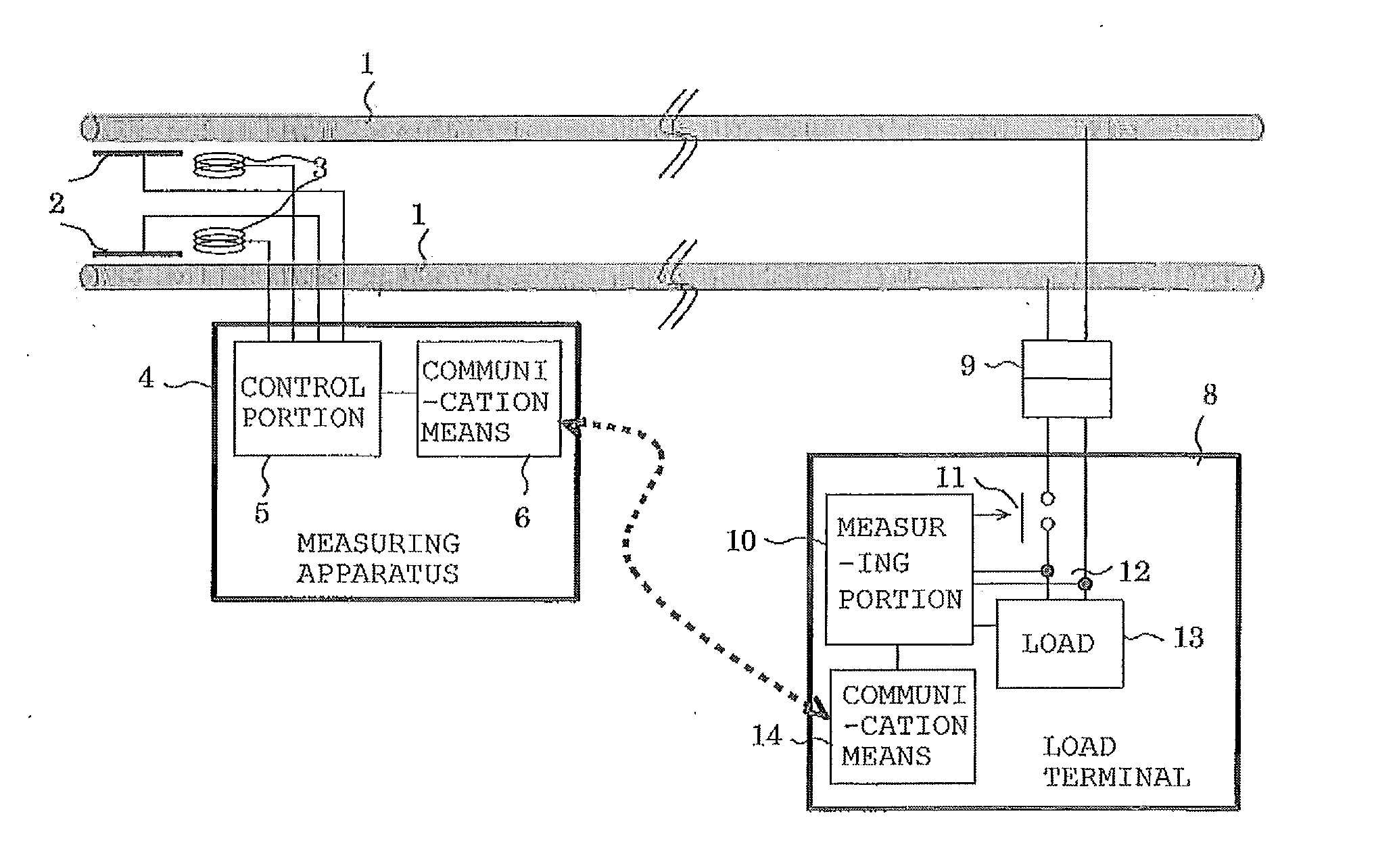
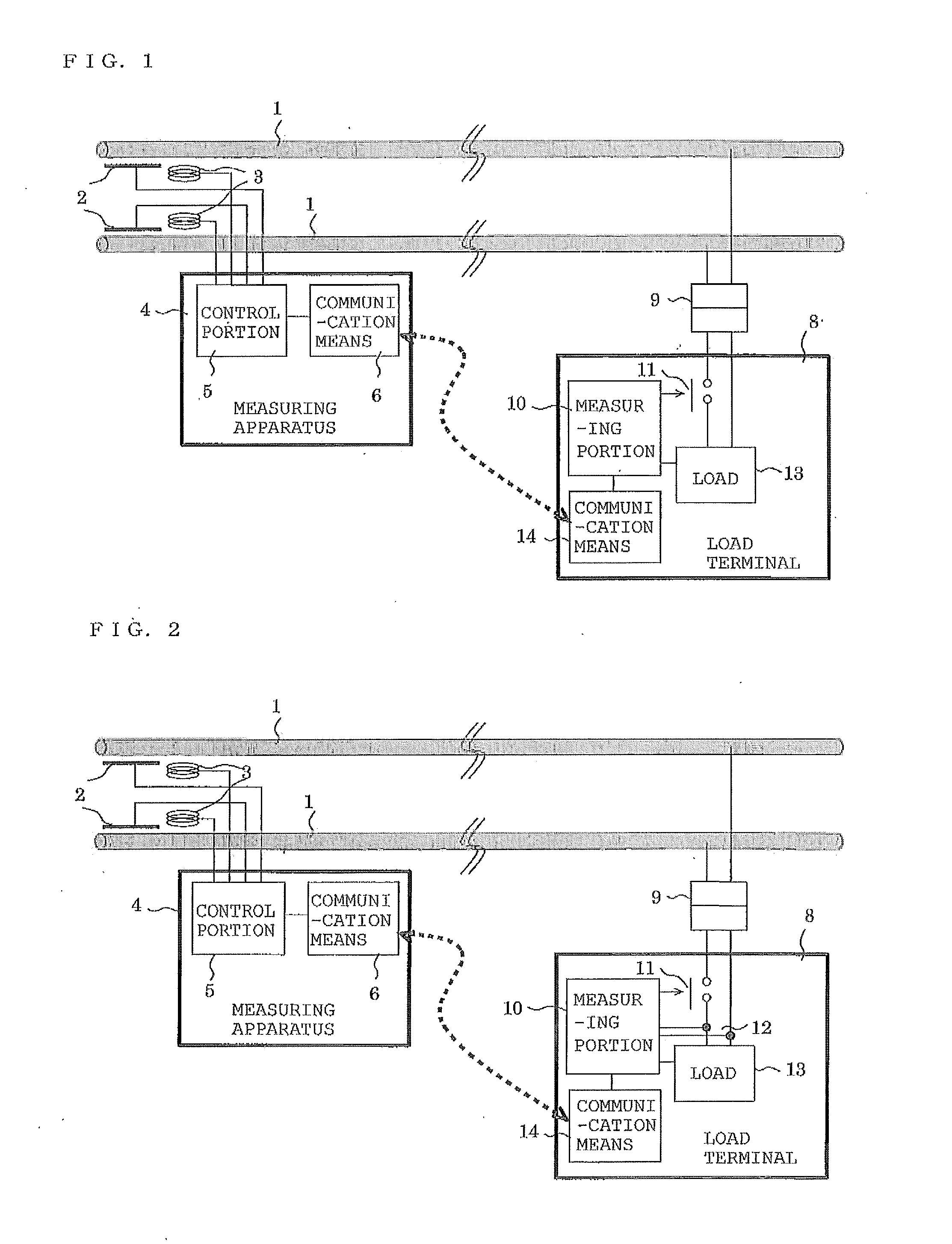
[0032]FIG. 1 illustrates the configuration of a power measuring system according to EXAMPLE 1 of the present invention. In FIG. 1, reference numeral 1 denotes a power line for supplying power to an electric device, 2 denotes a voltage sensor for observing a voltage waveform between two power lines 2 through electrostatic coupling, and 3 denotes a current sensor for observing, through electromagnetic coupling, a magnetic flux generated by a current that flows through each power line 1 due to a load including the electric device, etc., and for observing a current waveform. In the case of a general home, the voltage sensor 2 and the current sensor 3 are installed, for example, near an indoor-side wiring connection point in a main breaker of a distribution board. Reference numeral 4 denotes a measuring apparatus comprising a control portion 5 and communication means 6 for communicating with a load terminal 8. The voltage sensor 2 and the current sensor 3 are connected to the control por...

example 2

[0045]FIG. 2 illustrates the configuration of a power measuring system according to EXAMPLE 2 of the present invention. In FIG. 2, reference numeral 1 denotes a power line for supplying power to an electric device, 2 denotes a voltage sensor for observing a voltage waveform between two power lines 2 through electrostatic coupling, and 3 denotes a current sensor for observing, through electromagnetic coupling, a magnetic flux generated by a current that flows through the power line 1 due to a load including the electric device, etc., and for observing a current waveform. In the case of a general home, the voltage sensor 2 and the current sensor 3 are installed, for example, near an indoor-side wiring connection point in a main breaker of a distribution board. Reference numeral 4 denotes a measuring apparatus comprising a control portion 5 and communication means 6 for communicating with a load terminal 8. The voltage sensor 2 and the current sensor 3 are connected to the control port...

example 3

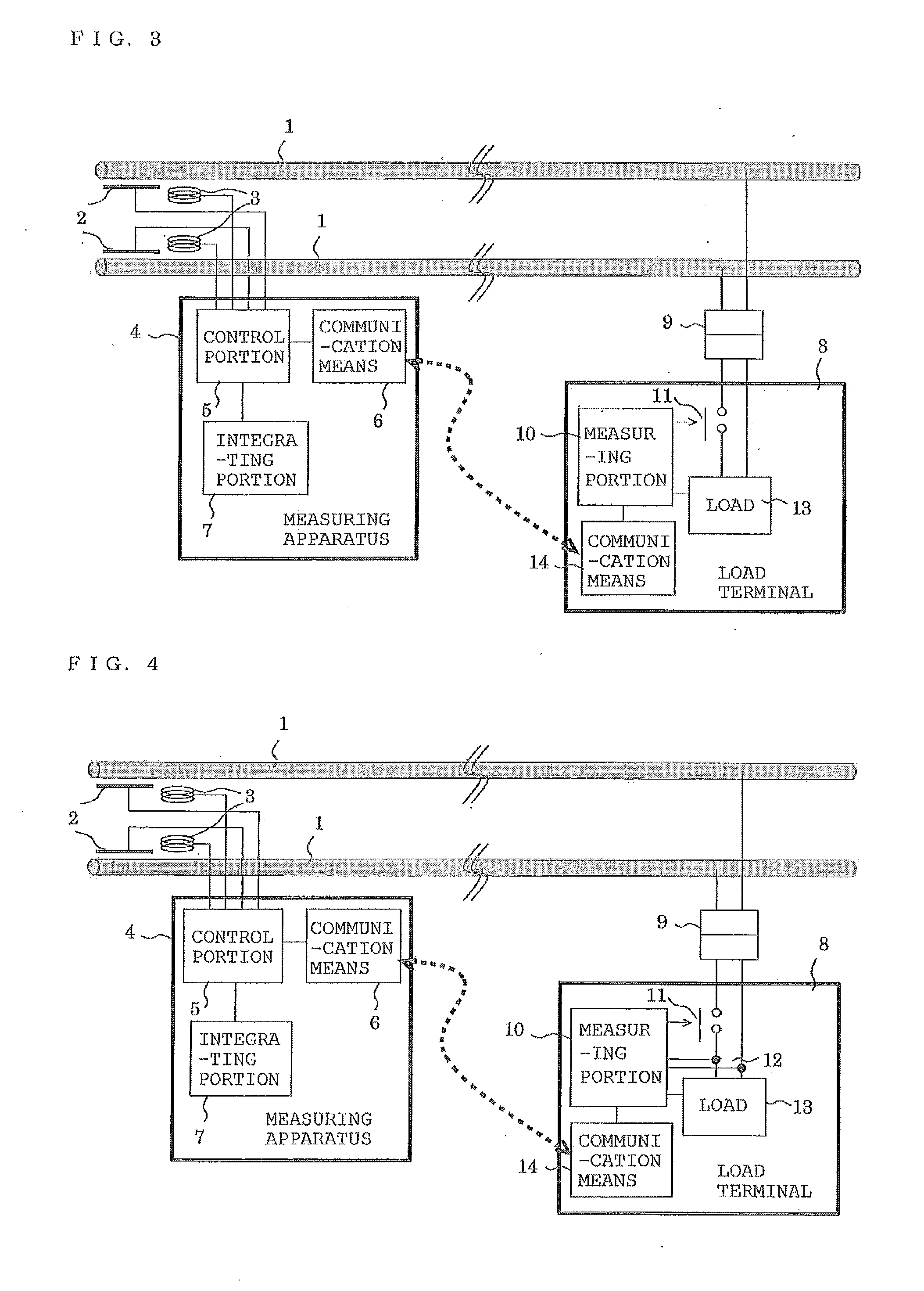
[0058]FIG. 3 illustrates the configuration of a power measuring system according to EXAMPLE 3 of the present invention. In FIG. 3, reference numeral 1 denotes a power line for supplying power to an electric device, 2 denotes a voltage sensor for observing a voltage waveform between two power lines 2 through electrostatic coupling, and 3 denotes a current sensor for observing, through electromagnetic coupling, a magnetic flux generated by a current that flows through each power line 1 due to a load including the electric device, etc., and for observing a current waveform. In the case of a general home, the voltage sensor 2 and the current sensor 3 are installed, for example, near an indoor-side wiring connection point in a main breaker of a distribution board. Reference numeral 4 denotes a measuring apparatus comprising a control portion 5 and communication means 6 for communicating with a load terminal 8. The voltage sensor 2 and the current sensor 3 are connected to the control por...


PUM


Abstract

A power measuring system, a measuring apparatus, a load terminal, and a device control system are provided, which need no special installation work to be made by any skillful professionals such as persons qualified for electrical work. A voltage sensor detects a voltage waveform of a power line in a noncontact manner, and a current sensor acquires a current waveform of the power line in a noncontact manner. A measuring portion of a load terminal operates a contact means to connect the power line and a voltage measuring terminal to measure a current flowing from the power line to a load and to calculate a voltage value from the measured current value and the load. The measuring portion of the load terminal transmits, in response to a request from a measuring apparatus, the measured current value and the calculated voltage value to the measuring apparatus via a communication means. A control portion of the measuring apparatus receives the current value and the voltage value from the load terminal via a communication means. The control portion calculates a power value based on the received current value and voltage value, as well as on the voltage waveform acquired from the voltage sensor and the current waveform acquired from the current sensor.

Description

TECHNICAL FIELD [0001]The present invention relates to a power measuring system for measuring power consumed by electric devices in a noncontact manner, which are installed in general homes, shops, small-to-medium sized buildings, etc., as well as to a measuring apparatus and a load terminal constituting the power measuring system. The present invention also relates to a device control system for measuring power consumed by electric devices, which are installed in general homes, shops, small-to-medium sized buildings, etc., and for controlling states of the devices based on the measured results.BACKGROUND ART[0002]In order to measure power consumed by electric devices which are installed in general homes, shops, small-to-medium sized buildings, etc., it has hitherto been required for professionals to set up a power meter by attaching a voltage transformer or a current transformer to a distribution board, for example. Also, when power consumptions of devices are controlled in a deman...

Claims


Application Information

Patent Timeline
IPC IPC(8): G01R19/00
CPCG01R11/17G01R21/133G01R21/06G01R35/04G01R15/142G01R19/2513
Inventor HIGUMA, TOSHIYASUKUSHIRO, NORIYUKIYABE, MASAAKI
Owner MITSUBISHI ELECTRIC CORP
Why Eureka
Try Eureka