Method and device for determining a foam density

a foam density and density technology, applied in measurement devices, instruments, scientific instruments, etc., can solve the problems of not being able to detect different foam structures, not being able to accurately determine the filling level, and only able to determine the decomposition rate of foams, so as to achieve the effect of little effort and little tim

Inactive Publication Date: 2010-12-02
KRONES AG
View PDF9 Cites 13 Cited by
  • Summary
  • Abstract
  • Description
  • Claims
  • Application Information

AI Technical Summary

Benefits of technology

[0009]The method here utilizes the effect that the foam brings about a scattering of the light beam. In the process, a differently high foam density causes a differently strong scattering, i.e. divergence of the beam. Highly dense foam which binds a high liquid quantity causes a strong scattering of the light beams. Reversely, the scattering is weaker if the foam binds less liquid, that means the foam is less dense.
[0023]It is furthermore advantageously possible to integrate the device into existing camera devices for filling level controls. Existing camera systems which are already installed in filling systems for filling level control can be thus retrofitted within little time and at little effort.

Problems solved by technology

However, due to the forming foam, it is difficult, if not even impossible, to accurately determine the filling level directly after filling, because for doing so, one actually has to wait until the foam has settled.
A determination of the liquid bound in the foam only on the basis of the dimensions of the foam often involves errors as the density of the forming foam varies, so that the bound liquid quantity does not only depend on the type of beverage but also varies from container to container.
These methods have the disadvantage that they cannot detect different foam structures.
Though methods for measuring foam are known, one can only determine decomposition rates of the foams with these methods.
However, no exact determination of the foam density is possible with this method.

Method used


Image

  • Method and device for determining a foam density
  • Method and device for determining a foam density
  • Method and device for determining a foam density

Examples


Embodiment Construction

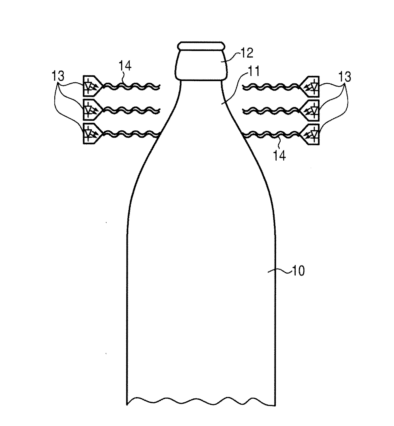
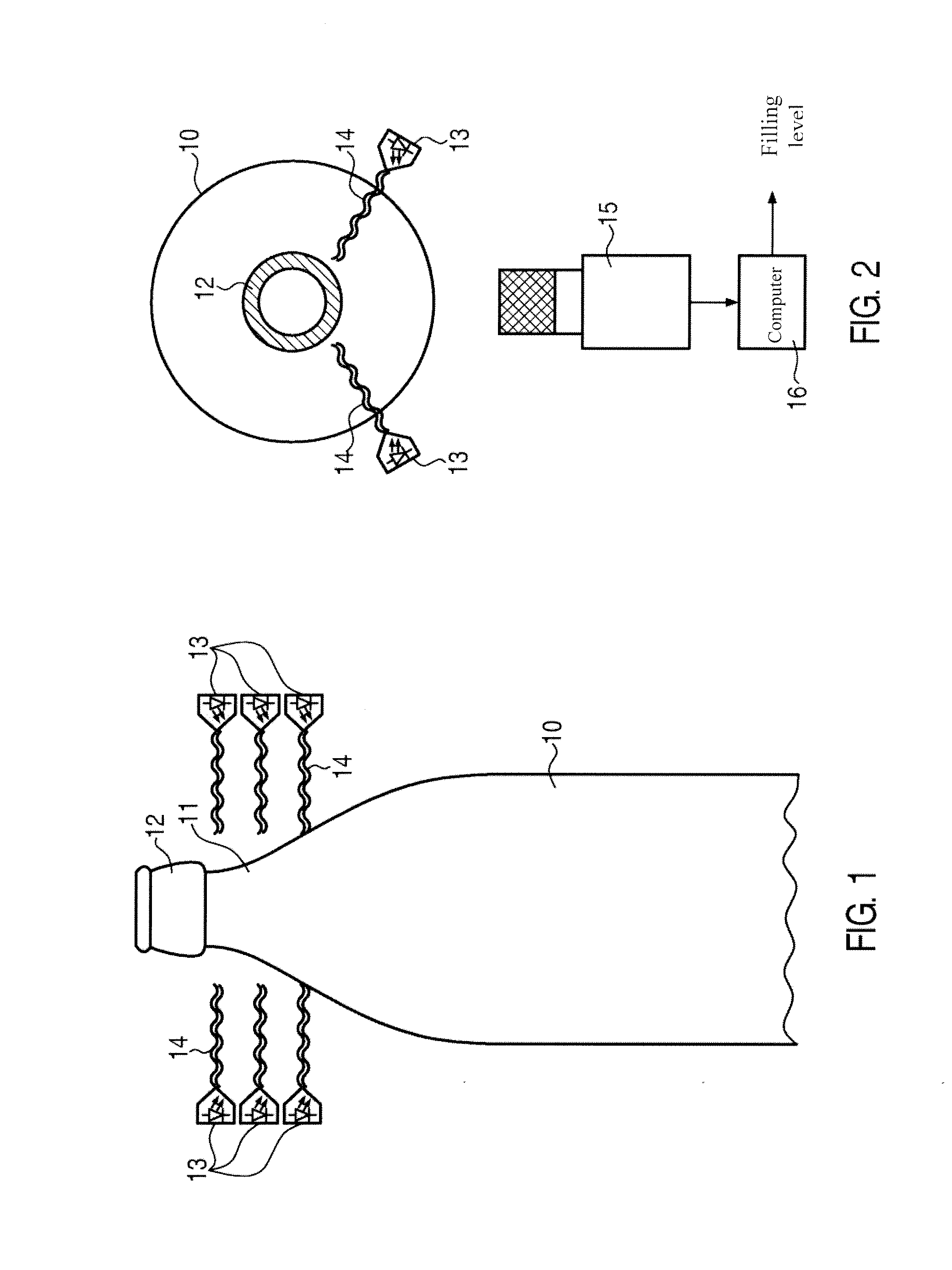
[0028]In FIG. 1, an upper area of a beverage container is represented. This is a beverage bottle 10 with a conically tapering neck of the bottle 11. The neck of the bottle 11 ends in a thickening opening area 12. The beverage bottle 10 is a commercially available narrow-neck bottle as it is often employed in the beverage industry, in particular in the beer industry.

[0029]In the area of the neck of the bottle 11, several light sources in the form of lasers 13 are laterally disposed in the represented embodiment. Two lasers 13 each lie in one plane. Altogether, six lasers 13 are arranged in three planes arranged one upon the other. Thus, the neck of the bottle 11 is surrounded by lasers 13 at least in an area underneath the opening area 12, the lasers 13 being disposed along a longitudinal axis of the beverage bottle 12.

[0030]The lasers 13 which are disposed in one plane are positioned to be offset with respect to each other at the circumference. This means that the respectively emitt...


PUM

PropertyMeasurementUnit
densityaaaaaaaaaa
foam densityaaaaaaaaaa
liquid quantityaaaaaaaaaa

Abstract

Method and device for determining a foam density of foam in beverage containers utilizing the Tyndall effect, and having a focused light bundle emitted into the foam by means of a light source, where the light bundle is refracted in the foam and a scattered ray becomes visible on a surface of the foam. Via a measurement of the contour of such a light spot, conclusions on the foam density can be drawn. For this, one or several lasers can be integrated into existing filling level measuring means which are coupled to the already existing measuring means.

Description

CROSS-REFERENCE TO RELATED APPLICATION[0001]The present application claims the benefit of priority of German Application No. 102009022691.5, filed May 26, 2009. The entire text of the priority application is incorporated herein by reference in its entirety.FIELD OF THE DISCLOSURE[0002]The disclosure relates to a method for determining the foam density of foam according to the preamble of claim 1 as well as to a device for this according to the preamble of claim 5.BACKGROUND[0003]In beverage filling systems, a layer of foam is often formed during the filling in particular of beverages particularly containing carbon dioxide into beverage containers, such as bottles. Depending on the type of beverage, more or less foam can be formed. In particular during the filling of beer, a lot of foam is often formed. Normally, it takes some time until the foam has settled, i.e. until the liquid quantity bound in the foam is released. To check the liquid quantity in the beverage container, the fill...

Claims


Application Information

Patent Timeline
Patent Type & Authority Applications(United States)
IPC IPC(8): G01N21/00
CPCG01N21/51G01N21/9027G01N33/146B67C3/007
Inventor PIANA, STEFAN
Owner KRONES AG
Why Eureka
Try Eureka