
Zoom lens with high optical performance and image pickup apparatus having the same

a zoom lens and high optical performance technology, applied in the field of zoom lenses, can solve the problems of difficult to obtain a high optical performance in a whole field, difficult to obtain a good optical performance in a whole zoom range, large amount of off-axis aberration is easily generated, etc., and achieves high optical performance, wide field angle, and high zoom ratio

Active Publication Date: 2010-12-02
CANON KK
View PDF8 Cites 9 Cited by
  • Summary
  • Abstract
  • Description
  • Claims
  • Application Information

AI Technical Summary

Benefits of technology

[0009]The present invention provides a zoom lens having a wide field angle and a high zoom ratio and also a high optical performance in a whole zoom range, and an image pickup apparatus having the zoom lens. In addition, the present invention provides a zoom lens capable of maintaining a good image with the high zoom ratio in performing an anti-shake operation.

Problems solved by technology

Although the high zoom ratio is easily obtained by strengthening the refractive power of the magnification varying lens unit, an aberration variation caused by the zoom operation (magnification varying operation) becomes large and it is difficult to obtain a good optical performance in a whole zoom range.
Although the field angle of the retro-focus type is easily widened, a large amount of an off-axis aberration is easily generated and it is difficult to obtain a high optical performance in a whole field angle because a whole lens system is asymmetric with respect to an aperture stop.
However, a space for arranging the anti-shake lens units is necessary and an decentration aberration is generated in performing the anti-shake operation, and therefore an image quality is deteriorated.

Method used


Image

  • Zoom lens with high optical performance and image pickup apparatus having the same
  • Zoom lens with high optical performance and image pickup apparatus having the same
  • Zoom lens with high optical performance and image pickup apparatus having the same

Examples


embodiment

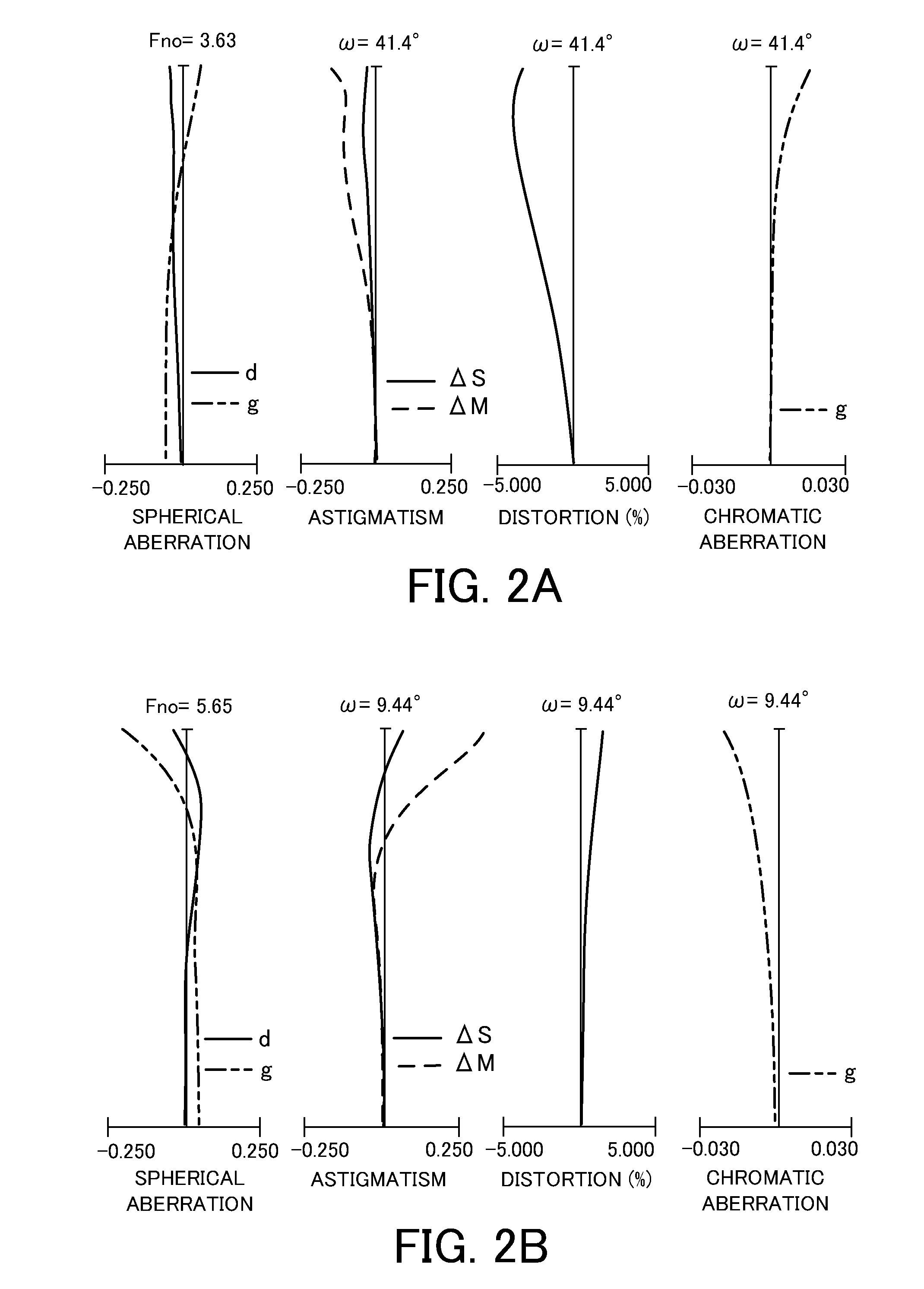
[0047]Hereinafter, Numerical embodiments 1 to 3 which correspond to Embodiment 1 to 3 respectively are shown. In each numerical embodiment, reference code “i” denotes an order of a surface from the object side, reference code “ri” denotes an i-th (an i-th surface) radius of curvature, and reference code “di” denotes an interval between the i-th surface and the (i+1)-th surface. Reference codes “ndi” and “vdi” denote a refractive index and Abbe's number of a material of an i-th optical member based on a d-line, respectively. Reference code “BF” denotes a back focus which is obtained by performing an air conversion. In aspherical surface data, aspherical surface coefficients which are represented by the following expression are indicated.

x=h2R1+1-(1+k)(hR)2+c4h2+c6h2+c8h2+c10h2+c12h2

[0048]In the expression, “x” is a displacement from a reference surface in an optical axis direction. “h” is a height in a direction perpendicular to the optical axis. “R” is a radius of a quadric surface ...


PUM


Abstract

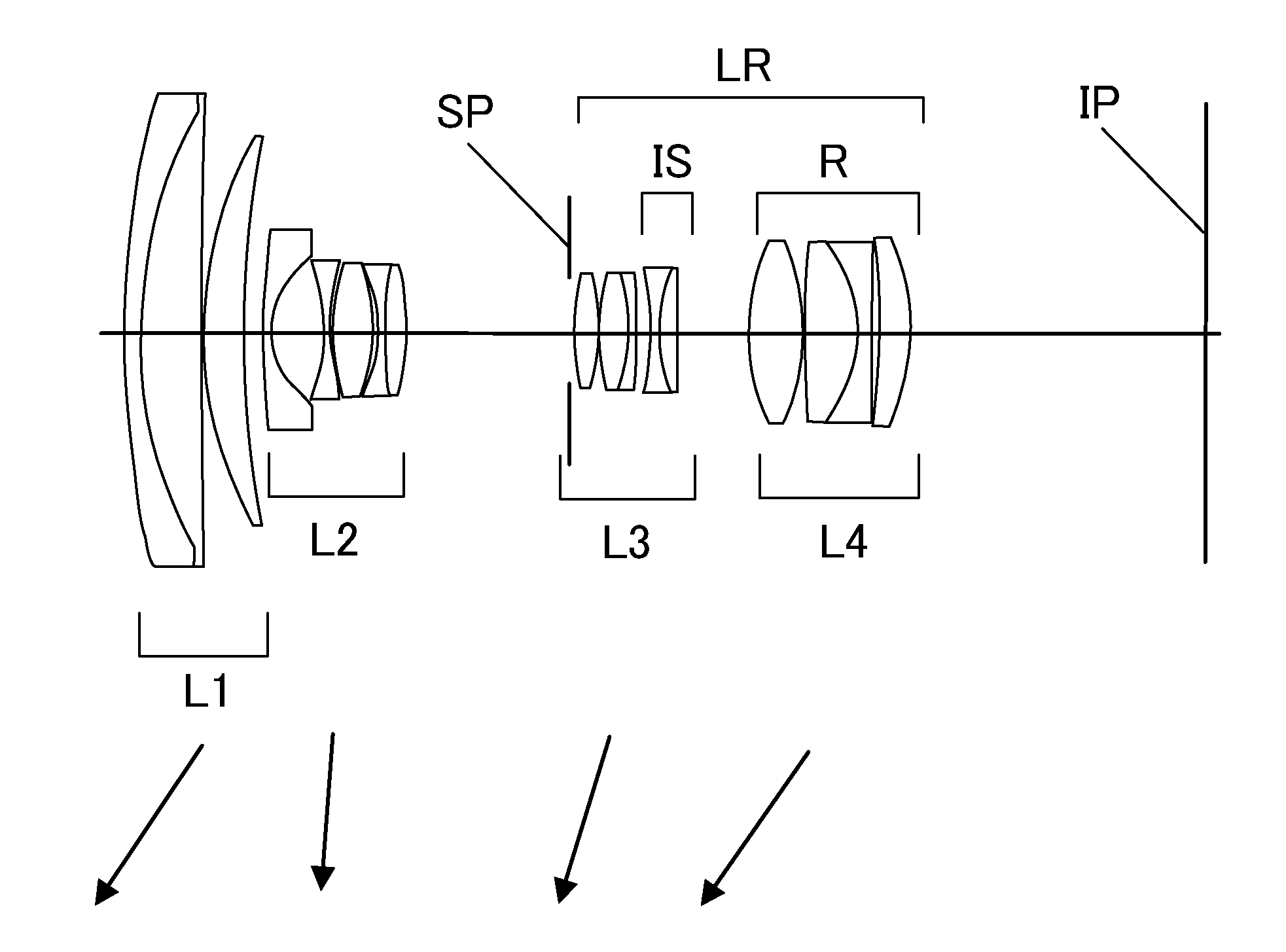
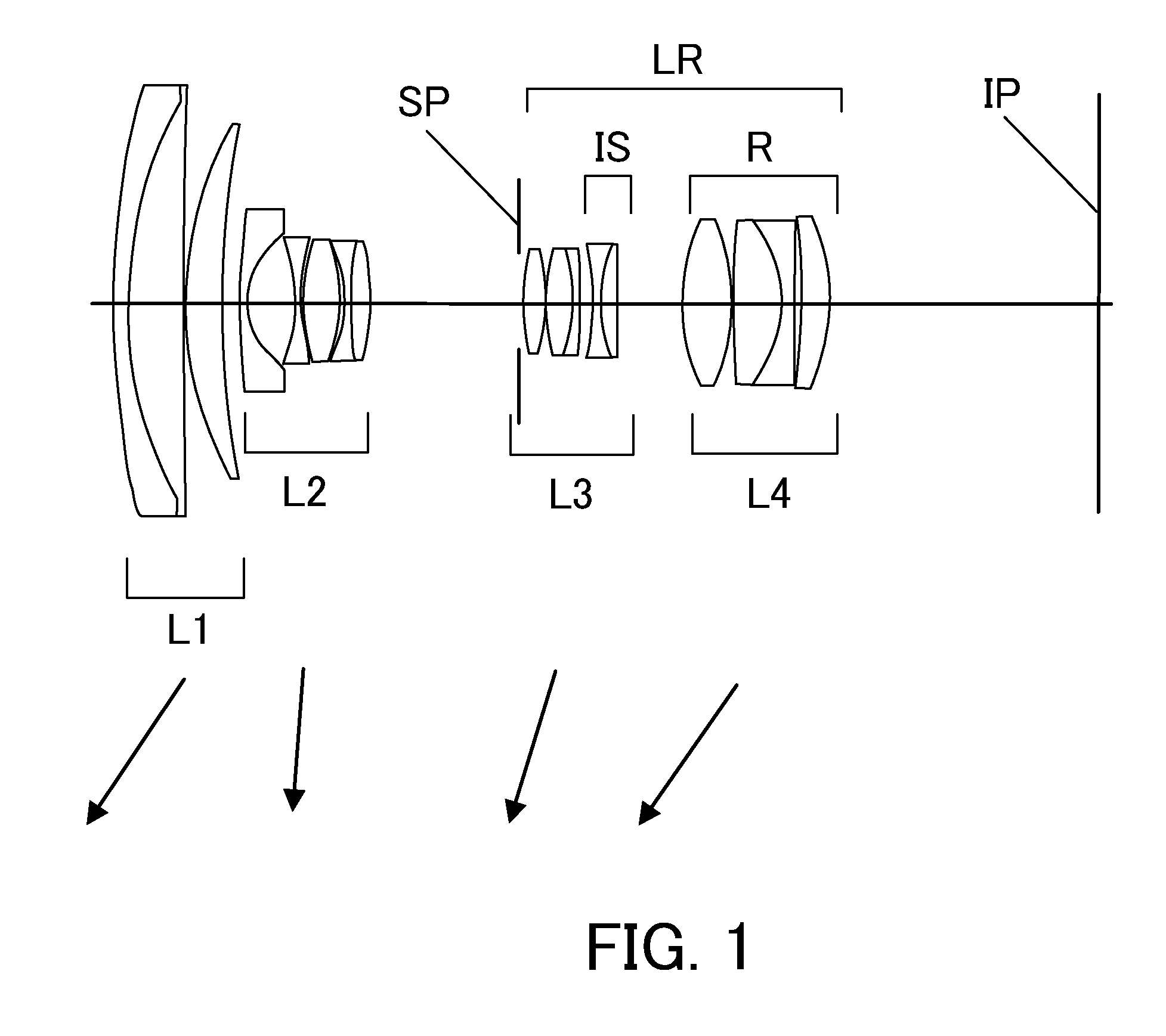
A zoom lens comprises a first lens unit having a positive refractive power, a second lens unit having a negative refractive power, and a rear group including at least two lens units and having a positive refractive power as a whole, in order from an object side to an image side. An interval of each of the lens units changes in a zoom operation, the rear group includes a lens unit R having a positive refractive power at the most image side, the lens unit R includes a lens having a concave surface at the image side and having an aspherical surface shape where a negative refractive power becomes stronger with increasing distance from an optical axis, and focal lengths f1, fR, and fw of the first lens unit, the lens unit R, and a whole system at a wide-angle end, respectively, are appropriately set.

Description

BACKGROUND OF THE INVENTION[0001]1. Field of the Invention[0002]The present invention relates to a zoom lens which is used for an image pickup apparatus such as a digital camera, a video camera, a TV camera, or a film camera.[0003]2. Description of the Related Art[0004]As an image pickup optical system which is used for an image pickup apparatus such as a video camera or a digital still camera using a solid-state image pickup element, a zoom lens having a wide field angle and a high zoom ratio and also a high optical performance in a whole zoom range and in an overall object distance is required. Further, the zoom lens is required to have an anti-shake function which corrects an image shake generated by a camera shake or a hand jiggling.[0005]A zoom lens which is constituted by four lens units having positive, negative, positive, and positive refractive powers in order from an object side to an image side is known (Japanese Patent Laid-open No. 2003-322795, and U.S. Pat. No. 6,975,4...

Claims


Application Information

Patent Timeline
IPC IPC(8): G02B15/14
CPCG02B15/173G02B27/646G02B15/14G02B15/143105
Inventor HATADA, TAKAHIRO
Owner CANON KK
Learn More