Method for ascertaining the axis of rotation of a vehicle wheel

Active Publication Date: 2010-12-02
BEISSBARTH
View PDF9 Cites 118 Cited by
  • Summary
  • Abstract
  • Description
  • Claims
  • Application Information

AI Technical Summary

Benefits of technology

[0008]An object of the present invention is to provide a method for ascertaining the axis of rotation of a vehicle wheel and therefrom, if necessar

Problems solved by technology

While markings of this type provide structures on the wheel that are easily detectable for measuring and analysis, they require additional effort.
In contrast, in previous methods and devices without special markings or using projected light, it is difficult to obtain exact and reli

Method used


Image

  • Method for ascertaining the axis of rotation of a vehicle wheel
  • Method for ascertaining the axis of rotation of a vehicle wheel
  • Method for ascertaining the axis of rotation of a vehicle wheel

Examples


Embodiment Construction

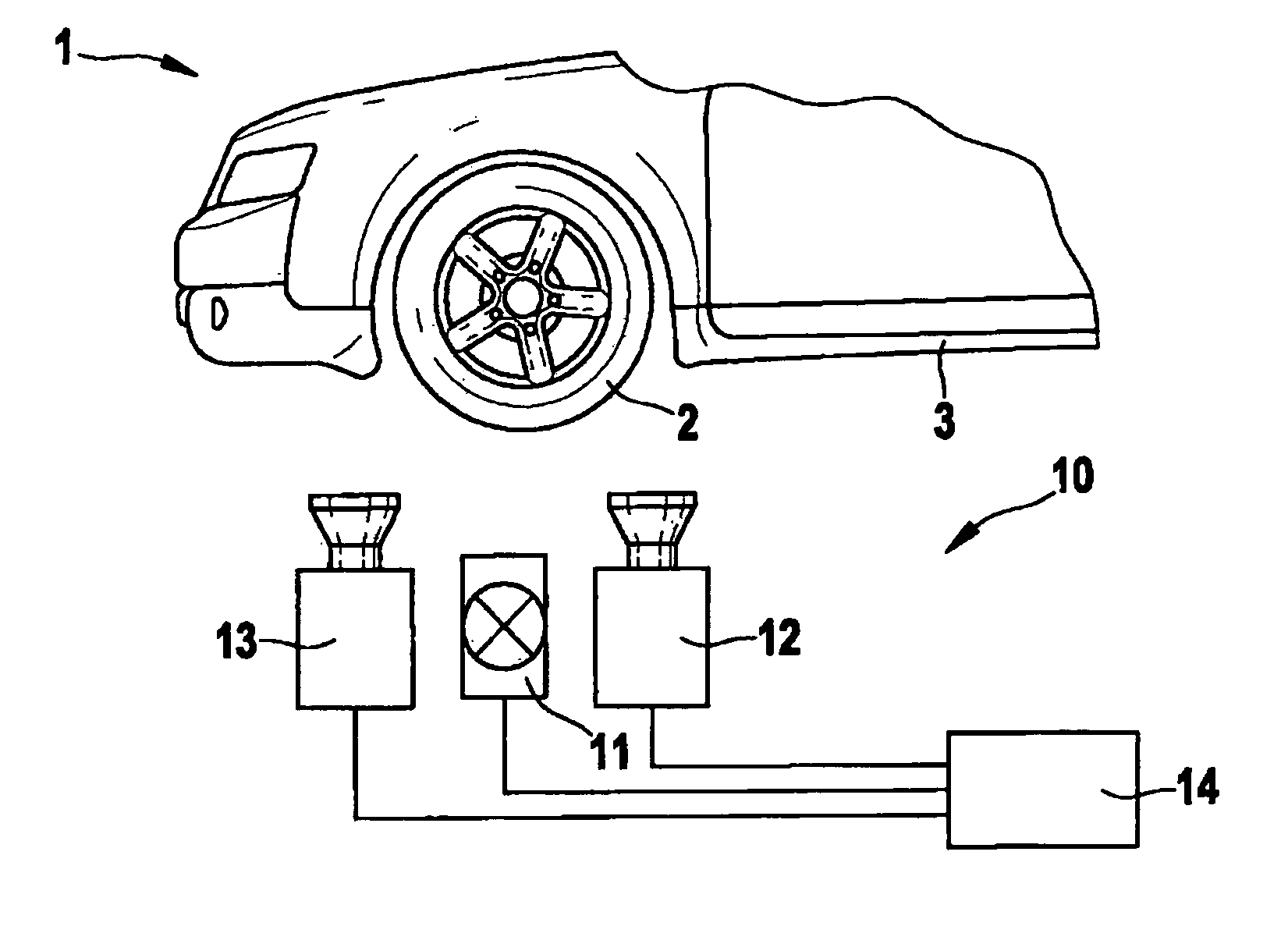
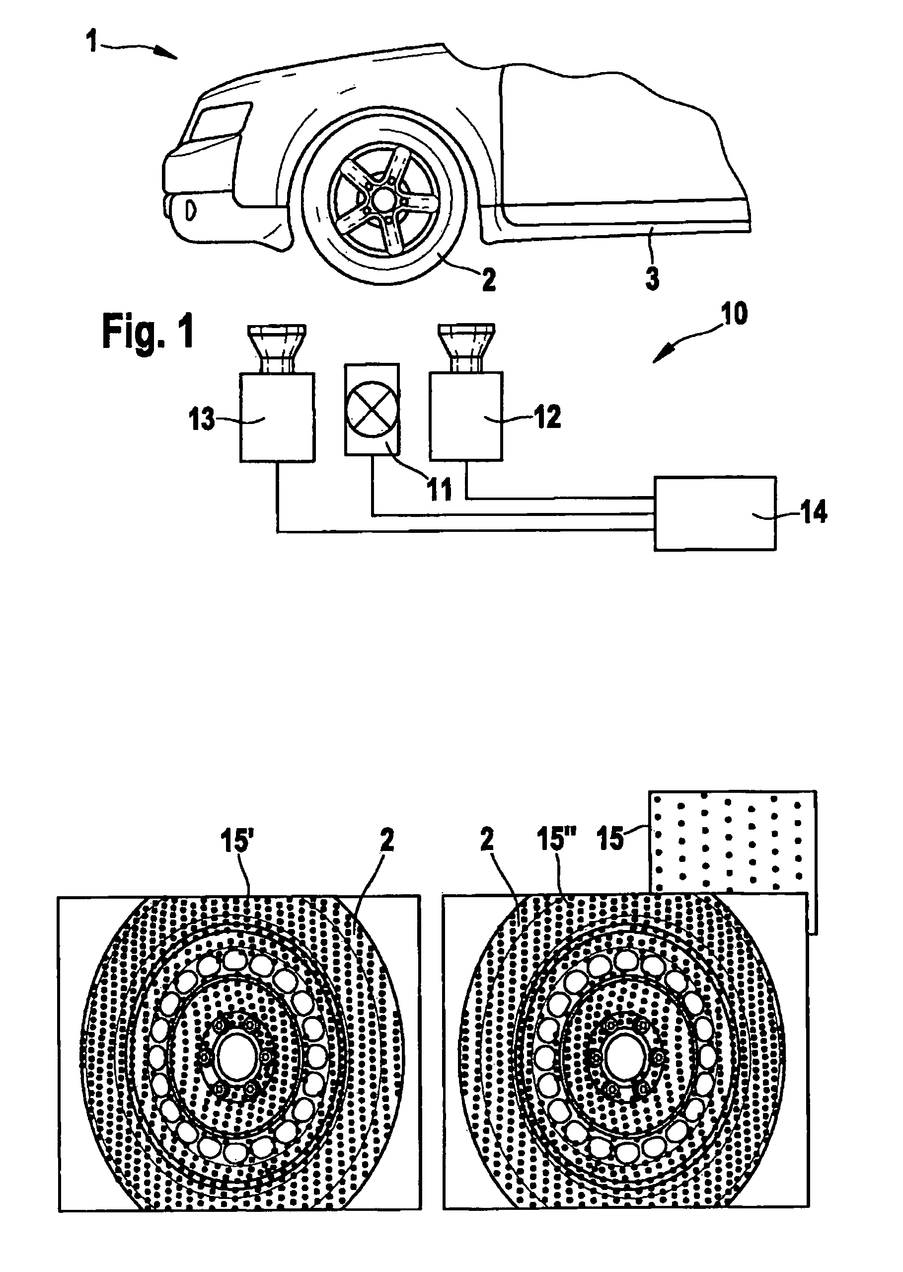
[0027]FIG. 1 shows a measuring environment for ascertaining the axis of rotation of a vehicle wheel 2 with the aid of a measuring device 10, vehicle 1 being capable of moving past measuring device 10. In addition to wheel 2, body 3 may also be included in the measurement, preferably in the surroundings of wheel 2.

[0028]Measuring device 10 has a projection device 11 for light patterns 15 (see FIG. 2) and two imaging sensor units 12, 13 situated in a predefined spatial position and direction thereto, and a control unit 14, which is connected for data transmission to projection device 11 and imaging sensor units 12, 13, positioned in stereo formation, and electronic devices for controlling projection device 11, imaging sensor units 12, 13, and possibly other connected components and for analyzing the data and displaying the measurement results.

[0029]FIG. 2 shows, in addition to light pattern 15, light patterns 15′ and 15″ reflected from the wheel, resulting from the view of the two ima...


PUM


Abstract

A method for ascertaining the axis of rotation of a vehicle wheel in which a light pattern is projected at least onto the wheel during the rotation of the wheel and the light pattern reflected from the wheel is detected by a calibrated imaging sensor system and analyzed in an analyzer device. Accurate and robust measurement of the axis of rotation and, optionally, of the axis and wheel geometry, in particular when the vehicle is passing by, is achieved in that a 3D point cloud with respect to the wheel is determined in the analysis and a parametric surface model of the wheel is adapted thereto; normal vectors of the wheel are calculated for different rotational positions of the wheel for obtaining the axes of rotation; and the axis of rotation vector is calculated as the axis of rotation from the spatial movement of the normal vector of the wheel.

Description

FIELD OF THE INVENTION[0001]The present invention relates to a method for ascertaining the axis of rotation of a vehicle wheel, in which a light pattern is projected at least onto the wheel during the rotation of the wheel and the light pattern reflected from the wheel is detected by a calibrated imaging sensor system and analyzed in an analyzer device.BACKGROUND INFORMATION[0002]A method and a corresponding device of this type are described in U.S. Pat. No. 4,745,469, where an axis measurement is performed on the basis of the ascertained axis of rotation, in particular the trail angle and the camber angle are ascertained, while the vehicle is on a chassis dynamometer. Using a projection system, laser lines or other patterns are projected onto the wheel or onto the tire. Using cameras, the patterns are imaged and the 3D coordinates are reconstructed on the surface from the camera coordinates and from the conventional arrangement of the cameras with respect to the projector via trian...

Claims


Application Information

Patent Timeline
IPC IPC(8): G06K9/00
CPCG01B11/2755G01B2210/146G01B2210/286G01B2210/28G01B2210/20
Inventor ABRAHAM, STEFFENHAJA, ANDREASKNOLL, CHRISTIANKALLMANN, ULRICHHAPPOLD, WALTER
Owner BEISSBARTH
Why Eureka
Try Eureka