Transfer device and image forming apparatus

a technology of transfer device and image forming apparatus, which is applied in the direction of electrographic process apparatus, instruments, optics, etc., can solve the problems of inability to form a sufficiently high quality image, and difficulty in transferring the toner image on the intermediate transfer member onto the recording paper sheet at a rate of 100%, so as to achieve smooth image quality and reduce uneven density

Active Publication Date: 2010-12-02
SHARP KK
View PDF4 Cites 21 Cited by
  • Summary
  • Abstract
  • Description
  • Claims
  • Application Information

AI Technical Summary

Benefits of technology

[0014]An object of the invention is to provide a transfer device and an image forming apparatus capable of forming an image of smooth image quality with little uneven density.

Problems solved by technology

However, for example, when a two-component developer is used, a charge amount held by a toner is easily changed depending on the surrounding environment or the using situation and thus is unstable as transferring performance using the electrostatic force, therefore, it is difficult to transfer the toner image on the intermediate transfer member onto the recording paper sheet at a rate of 100%.
In the image forming apparatus described in JP-A 9-146381, although it is described as excellent in a cleaning property of the intermediate transfer member and in transfer efficiency from the intermediate transfer member to the recording paper sheet, and especially there will be no occurrence of local transfer failure, it is not possible to form a sufficiently high quality image since as a bias waveform to be used, a constant alternating current component is merely superimposed on a direct current component.

Method used


Image

  • Transfer device and image forming apparatus
  • Transfer device and image forming apparatus
  • Transfer device and image forming apparatus

Examples


Embodiment Construction

[0050]Now referring to the accompanying drawings, embodiments of the invention are described in detail below. Note that, in this specification and drawings, the components having substantially the same functions are denoted by the same reference numerals so that repeated description will be omitted.

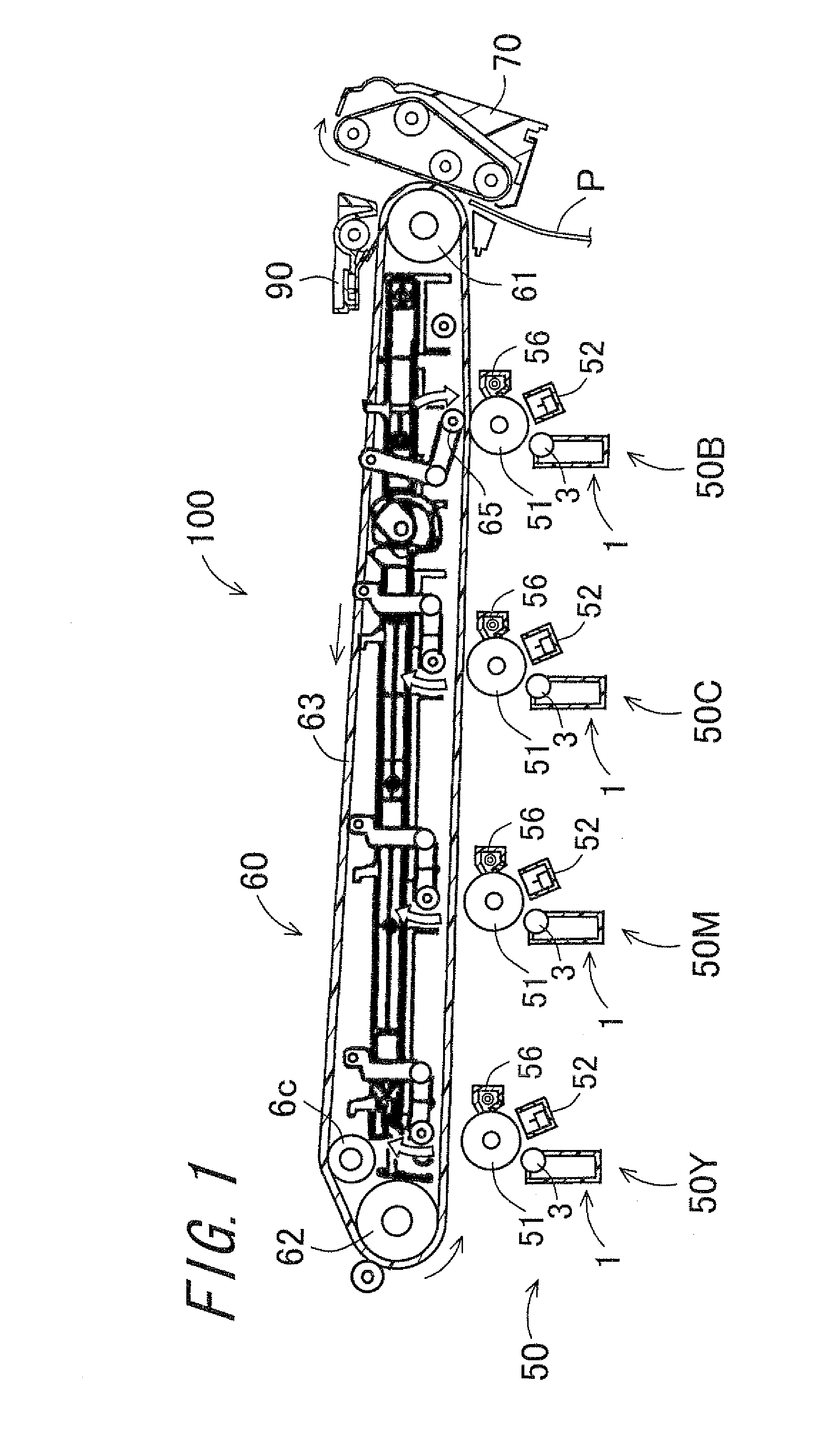
[0051]First, a configuration of a first embodiment of an image forming apparatus according to the invention will be described with reference to the drawing. FIG. 1 is a vertical cross sectional view schematically showing an overview of an entire configuration of an image forming apparatus 100 according to the first embodiment. Note that, for simplicity, FIG. 1 only shows an example of the image forming apparatus 100 of this embodiment mainly with principal components, which is not limited to a configuration of an image forming apparatus that comprises a transfer device according to the invention.

[0052]The image forming apparatus 100 is a tandem type color image forming apparatus capable o...


PUM


Abstract

A transfer device and an image forming apparatus capable of forming an image of smooth image quality with little uneven density, are provided. An alternating voltage is applied so that a first period in which a first peak-to-peak voltage Vpp(1) is applied and a second period in which a second peak-to-peak voltage Vpp(2), lower than the first peak-to-peak voltage, is applied are alternately repeated. In the alternating voltage to be applied, a transfer side potential to shift a toner from an intermediate transfer belt to recording paper sheet and an opposite transfer side potential to shift the toner from the recording paper sheet to the intermediate transfer belt are applied so as to alternate with each other. When f1 denotes a frequency of the first period and f2 denotes a frequency of the second period, f1=f2 is satisfied.

Description

CROSS-REFERENCE TO RELATED APPLICATION[0001]This application claims priority to Japanese Patent Application No. 2009-133484, which was filed on Jun. 2, 2009, the contents of which are incorporated herein by reference in its entirety.BACKGROUND OF THE INVENTION[0002]1. Field of the Invention[0003]The present invention relates to a transfer device and an image forming apparatus that transfer a toner image formed on an intermediate transfer member onto a recording paper sheet by applying an alternating voltage superimposed on a direct current voltage.[0004]2. Description of the Related Art[0005]In an electrophotographic image forming apparatus, a development method has been employed in which a surface of an electrostatic latent image bearing member (for example, a photoreceptor) is charged and an image is exposed to the charged region to from an electrostatic latent image, and the electrostatic latent image is developed so as to be made visible (developing).[0006]As such a development ...

Claims


Application Information

Patent Timeline
Patent Type & Authority Applications(United States)
IPC IPC(8): G03G15/16
CPCG03G15/1605G03G15/1675
Inventor AIMOTO, TOYOKAHAMADA, TOSHIMASA
Owner SHARP KK
Why Eureka
Try Eureka